Inderdeep Singh ılılılı

Author Archives: Inderdeep Singh ılılılı

Configuring BGP Route Maps

Today I am going to talk about the next step in the BGP. As we discussed on BGP Synchronisation and BGP multihop concept in my earlier articles. If you would like to have a look on that topics please check with the below links for your references.

BGP Synchronization Rule
BGP Load balancing ebgp-multihop

Some of the other articles on the BGP where we have BGP basics , BGP configurations on HP Routers and other articles are

BGP Basics Overview
Cisco Routers Sample BGP Configurations : Quick and Easy
Juniper Routers Sample BGP Configurations : Quick and Easy

In this article, I will take through the concept of the route maps and the configuration of the route maps in the BGP environment. All these configurations showing below will be on Cisco router.

Why we are using the BGP route maps, well route maps are used to control BGP routing information. Route maps are to define the condition by which routes are redistributed between routing domains.

Note : Route maps cannot be used to filter incoming BGP updates based on IP address. You can, however, use route maps to filter outgoing BGP updates based on IP address.

With the use of Continue reading

BGP Synchronization Rule

Today I am going to talk about one of the basic feature of the BGP named as BGP Synchronization. Your first question : what is BGP Synchronization ? 

BGP Synchronization means that the BGP should not advertise a route until all of the routers within the AS have learned about the route via an IGP. Hope it clears the concept. Let me explain you in another way. It means if you got a ebgp route from the external neighbor via router A (as a assumption) and you want to send it to router B which is connected to another ebgp neighbour, the routes can only be learned to router B once learned by internal routers via IGP protocol.

Let me take an topology and explanation to it and further we can go with the configuration where we will disable the Synchronization as we don't want the traffic to be known to the IGP protocol.


Fig 1.1- BGP Synchronization


As shown in the above topology, if Router C sends updates about network 170.10.0.0 and received by  Router A. Now Routers A and B are running IBGP as shown in the diagram so Router B receives updates about network 170.10. Continue reading

BGP Load balancing ebgp-multihop

Today I am going to talk about the BGP configuration where i will tell you about the load balancing between the two links connecting two service providers via BGP protocol. We have two different methods to achieve this one is use of ebgp multihop command or the other way is to use the ttl security command and both these methods are applicable on the BGP neighbor command.

In this article, We are going to take through the ebgp multihop command on to the neighbours between two service providers. I knew many of you already knew the load balancing concept in the BGP.

In my example, I am taking two serial links between two routers which shares the e-BGP information between them which means each router belongs to the specific AS number. Below is the topology for your reference.

Fig 1.1- use of ebgp multihop
In the above topology, Router A is in AS100 have two serial links connected to Router B which is in AS 200 and for both the links, e-bgp is sharing information.

Below is the configuration on Router A and Router B for your reference. All the IPs and the topology uses here has no relevance Continue reading

Configuring Voice VLANs

Today I am going to talk about the Voice VLAN. The Voice VLAN feature enables the VLAN to carry the voice traffic. So you have a switch with is connected to the IP Phones, it can be of Cisco Avaya or any other and is connected to the specified VLANs or you can name them Voice VLANs in your network. So when switch is connected to the IP phones, the connected switch sends the voice traffic with layer 3 IP precedence and Layer 2 class of service in short name as COS values which are set as default of value 5. That is the reason because the sound quality of an IP phone call can deteriorate if the data is unevenly sent, the switch supports quality of service (QoS) based on IEEE 802.1p CoS. 

Fig 1.1- Sample Topology- Switch and IP Phone


We can configure an access port with an attached Cisco IP Phone to use one VLAN for voice traffic and another VLAN for data traffic from a device attached to the phone. We can configure access ports on the switch to send Cisco Discovery Protocol (CDP) packets that instruct an attached phone to Continue reading

Providers Edge to Edge VPLS Configuration on Cisco ASR 9000 Series Routers

Today I am going to talk about the VPLS configuration on Cisco ASR 9000 series routers. Before we will start with the configuration part, lets talk about the basics of the VPLS.

VPLS stands for Virtual Private LAN Service and enables geographically separated local-area network (LAN) segments to be interconnected as a single bridged domain over an MPLS network. So with the help of VPLS customer can extend the Layer 2 traffic across the globe on MPLS enabled service provider network. 

If customer wants to share the L3 information with the service provider to route it from their networks towards the remote site, then we can use routing at the edges of the PE routers and MPLS in the core while if customer don't want to share the L3 information with the service provider they always go with the VPLS type of services where we have L2 protocols like Frame-Relay, Ethernet, ATM services at the edges of the PE routers and MPLS on the core. 

This is the basic difference between the MPLS and VPLS technologies. Some times you saw like EoMPLS ( Ethernet over MPLS) which is another VPLS technology as Layer 2 ethernet information shared over Continue reading

DMVPN Configurations on Juniper Router

Today I am going to talk about the configurations of DMVPN on Juniper routers and then associate Dynamic VPN with remote clients step by step. I talked about DMVPN earlier in my articles as well where i explained the basics of the DMVPN. I promised at that time that I will come up with the configurations of DMVPN on each and every vendor. Now I am coming up with the DMVPN configurations on Juniper routers first and I will come up with the configurations on Cisco, Huawei and HP routers later on.

Below are some of the links where i started with the DMVPN explanations
DMVPN Basics
DMVPN Vs IPSEC Basics
Quick Comparison: IPSEC vs DMVPN vs EasyVPN vs GETVPN


The configurations used here are for the demo purposes and has no relevance with any of the live and the enterprise networks. What kind of Topology it looks like, So i am pasting here the sample DMVPN topology and has no relevance with the configuration defining below. The configuration is just for your reference to take it further.

Fig 1.1- Sample DMVPN Topology

To configure the VPN tunnel, 
First you need to configure the IKE policy.

OSPF Show Commands : Cisco, Juniper, Huawei, HP and Arista Networks

I am going to talk about the OSPF show commands in this article on different vendors which includes Cisco, Juniper, Huawei, HP and Arista Networks. These commands are working as per the device you have. Please let me know if you knew any other commands in general for OSPF in different platforms which includes Cisco, Juniper, Huawei, HP and Arista Networks.

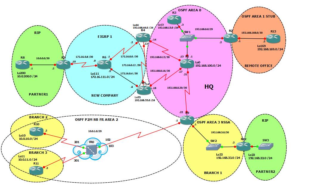
Fig 1.1- Sample OSPF topology

Above is the sample topology and below are the sample OSPF show commands which will help you to troubleshoot OSPF in your network for the various platforms

Cisco OSPF show Commands
ttlbits@cisco#sh ip ospf
ttlbits@cisco#sh ip ospf data
ttlbits@cisco#sh ip ospf database database-summary
ttlbits@cisco#sh ip ospf neighbor
ttlbits@cisco#sh ip ospf nei det
ttlbits@cisco#sh ip ospf int
ttlbits@cisco#sh ip ospf virtual-links
ttlbits@cisco#sh ip ospf database self-originate
ttlbits@cisco#sh ip ospf adv-router X.X.X.X

ttlbits@cisco#sh ip ospf stat

Juniper OSPF show Commands
ttlbits@juniper> show ospf route
ttlbits@juniper> show ospf route detail
ttlbits@juniper> show ospf route extensive
ttlbits@juniper> show ospf3 route detail
ttlbits@juniper> show ospf route topology voice
ttlbits@juniper> show ospf database
ttlbits@juniper> show ospf database detail
ttlbits@juniper> show ospf database extensive
ttlbits@juniper> show ospf Continue reading

Configuring Private VLANs on Juniper Switches

Thanks for the huge support on all my previous articles. Today I am going to talk about the Private VLANs configuration on the Juniper Switches. Earlier I wrote a article where i talk about the basics of the Private VLANs and the vendors supported to Private VLANs. If you want to have a look on that article, please go through the below mentioned link for the Private VLANs

Basics of Private VLANs

I am sure after reading the above article you will come to know about the basics of the Private VLANs. In this article I am going to cover the Configurational part of the Private VLANs on Juniper Switches, as it is demanded by some of the candidates on the blogs.

I will soon come up the configuration and the topology for the Private VLANs on Cisco and Huawei as well in another article.

A lot of people asking me about the VLANs, before starting with the configuration of the Private VLANs, let me quickly go through the VLANs and Private VLANs.

VLANs : Virtual Local Area Networks
VLANs is the way to partition the various Layer 2 network with in one Local Area Network which simply means that Continue reading

Juniper Q-fabric Solution

Today I am going to talk about the Juniper Q-Fabric solution which is an alternate approach to the Cisco SDA - Software Defined Access solution in the market. If you check the SDA in detail, Cisco uses Fabric network and on the top of it they are using LISP and VXLAN in the campus environment as a overlay protocols. On top of it there is Automation, Analytics and Authentication which is then connected via different APIs in the network.

Let's talk about the Q-fabric which is introduced by Juniper in the market. The so called Q-fabric of juniper is composed of multiple components working together as a single switch to provide high-performance, any-to-any connectivity and management simplicity in the data center or in the campus as well that depends where the requirement actually have.

QFabric System flattens the entire data center network to a single tier where all access points are equal, eliminating the effects of network locality and making it the ideal network foundation for cloud-ready, virtualized data centers.

With the help of QFabric System you can actually improves application performance with low latency and converged services in a nonblocking, lossless architecture that supports Layer 2, Layer 3, Continue reading

Juniper VXLAN Configs: Configuring VXLANs on Juniper MX Series Routers

Today I am going to have the scenario where i am going to explain and provide you the VXLAN configurations on Juniper MX series router with the topology. VXLAN as you already knew that these are Virtual extensible LAN used to extend the layer 2 and layer 3 traffic across the public or private network or generally in the case of two datacenter connectivity.

I wrote some of the articles where i put some of the configurations and the basic information about the VXLAN. Below are the links if you want to review the same

Above are some of the topics on the VXLAN and I will come up with more VXLAN topics in the near future. Below is the topology of the VXLAN where VXLAN is configured to run on a default bridge domain. In this topology, the VTEP interfaces sources are configured to the loopback address, and VLAN groups are configured under bridge domains with VXLAN enabled. Here the interfaces are configured for VLAN tagging and Continue reading

IPSEC configurations between two routers across Internet

Today I am going to talk about the IPSEC configurations between two routers in the LAN segments. I know most of you understand the theoretical and the configurational part of the IPSEC in details. In this article I am just taking the example of the IPSEC configuration between two routers in a LAN network or you can say that it is a LAN to LAN IPSEC configurations between two routers.

The article is based in the assumption of the routers as i took Cisco routers in the example, These models are Cisco 3640 routers which is i knew end of sale as of now. Cisco 3640 is a modular Access routers and uses in small or branch offices.


Lets take below mentioned topology to understand the configuration of IPSEC on one of the router named Router A. So in the below example we have the LAN to LAN IPSEC tunnel between the routers via Internet link. where the host behind the router A wants to talk to host behind the router B. Make sure you know that IPSEC is generally used where the intermediate network is Internet via which you have the secure connectivity.


The other way to connect the same Continue reading

BGP Configurations on HP Routers

Today I am going to talk about the BGP configurations on the HP routers. I already posted the articles on the BGP configurations earlier where i defined the basic configurations on the Cisco and Juniper routers. Apart from these configurations I already put the basic information of the BGP as well. Below are some of the articles for which you can refer to study yourself step by step.

BGP Basics
BGP basics on Juniper Routers
BGP configurations on Cisco routers

Today I am going to have the basic configurations on HP routers with the topology. Below is the basic topology and the basic BGP configuration as below. The Topology and the IP addresses used here are only for the demo purposes and has no relevance with any of the live or enterprise networks.

Below is the demo topology showing the use of the HP routers where BGP is configured in the MPLS environment. This is just a example to showcase the topology. I will come up with the configurations on HP routers in the MPLS environment in later stage. As of now first we need to talk about the basic BGP on the HP routers and step by step we Continue reading

Cisco Datacenter: Default Cisco OTV Configurations

Today I am going to talk about the Cisco OTV configuration and what components we need to configure when you are extended your L2 traffic over the L3 interface between the two Datacenter. 

What is Cisco OTV ?
Cisco OTV stands for Overlay Transport Virtualization, So OTV is a Cisco propriety protocol used in Cisco Datacenter environment basically on Cisco Nexus device Cisco Nexus 7k to extend the L2 traffic via L3 route between two different datacenter. 

OTV will provides a native built-in multi-homing capability with automatic detection, critical to increasing high availability of the overall solution. Cisco OTV has the concept of dynamic encapsulation for Layer 2 flows that need to be sent to remote locations. 

Each Ethernet frame is individually encapsulated into an IP packet and delivered across the transport network. Cisco OTV eliminates the need to establish virtual circuits, called Pseudowires, between the data center locations and you can say that it os one of the demanding technology in datacenter environment where you have Cisco Nexus devices.

Cisco OTV required the one single VDC to work, it means if you are going to have a one Cisco Nexus 7k switch you need to have the separate Continue reading

VTP modes and versions : VTPv1, VTPv2 and VTPv3

This topic is basically on the VLAN trunking Protocol which is called as VTP. I am talking about this topic as i am getting a lot of queries about the VTP protocol. Some of the questions i will summarised with this article. There are some of the questions which often asked at the time of the interview and are the basic questions.

Below are the questions about the VTP.
  • So what actual VTP do ? 
  • How we manage VLANs with the VTP ?
  • What are the various versions of VTP ?
  • How they differ from each other ?
  • what is the range of the VLANs supported ?
  • What is VTP Pruning ?
  • What are VTP modes ?
  • What are the different kinds of VTP advertisements ?

I understand there might be more queries on the VTP but let's start with the general talk about the VTP first. May be with this article most of the queries will be understandable.

Fig 1.1- Sample Switched Network

So VTP is a called as Layer 2 messaging protocol that contains VLAN configuration information  by managing the addition, deletion, and renaming of VLANs within a VTP domain. A VTP domain (also called a VLAN management domain) is made up of one Continue reading

Brocade : Zone‐Based Firewall

Today I am going to talk about the configuration of the Brocade router as Zone-Based Firewall. The first query in your mind will be that what is this zone based firewalls are ?

Well Zone based Firewalls are interfaces that are grouped into security “zones,” where each interface in a zone has the same security level.

In the Zone Based Firewalls, the packet-filtering policies are applied to the traffic flowing between the various zones in the network which is defined by the network administrator . So the concept is simple that the traffic flowing between interfaces that is there in the same zone is not filtered and flows freely because the interfaces share the same security level and the traffic flowing between the different zones will be filtered accordingly as security level can be different for different zones.

I will come up the Zone based Firewalls for Cisco soon in another article where i can share the configurations with the topology. This article is purely of Brocade where it is worked as Zone Based Firewall.

So below is the network where we defined three different zones which is defined by network administrator as per the demand in the network. The Zones are

OSPF Configurations in Huawei Routers

Today I am going to talk about the basic configuration of OSPF in Huawei Routers. There is already have a article on OSPF configuration on Cisco routers
OSPF Basic configuration Step by step on Cisco Routers

Apart from the above we have another articles on OSPF as shown below
OSPF Basics
OSPF Point to Multipoint Configuration- Cisco and Juniper
OSPF States
Difference between OSPF and RIP

Lets take an Topology here and below is the diagram for the configuration. We have the following topology as :

  • Router A is connected between Area 1 and Area 0
  • Router B is connected between Area 2 and Area 0
  • Router C is a internal Area 1 Router
  • Router D is a internal Area 2 Router
  • Router E is a internal Area 1 Router
  • Router F is a internal Area 2 Router


Fig 1.1-


# Configure Router A 
Below is the basic configuration of OSPF on Router A
[TTLBITS_A] router id 1.1.1.1
[TTLBITS_A] ospf 1
[TTLBITS_A-ospf-1] area 0
[TTLBITS_A-ospf-1-area-0.0.0.0] network 192.168.0.0 0.0.0.255 
[TTLBITS_A-ospf-1-area-0.0.0.0] quit 
[TTLBITS_A-ospf-1] area 1
[TTLBITS_A-ospf-1-area-0.0.0.1] network 192.168.1.0 0. Continue reading

Dark Fiber and Cisco OTV – Basic Approach and connectivity

Today I am going to discuss on the connectivity of the two datacenter and in the Active-Active state or you can called them as Connecting Multiple Active Datacenter with OTV and Dark Fiber.

First let's talk about the technologies, Cisco OTV is a Overlay Transport Virtualization technology and is used to extend the LAN segments across the datacenter or in other words you can say that extending the Layer 2 traffic over the Layer 3 network.

Note : Cisco OTV supports on Cisco Nexus 7K series switches and is not supported in Cisco Nexus 9K Switches.

Cisco OTV- Overlay Transport Virtualization technology
As I said, that Cisco OTV is the way to extend your layer 2 network across the datacenter via the Layer 3 links. OTV actually works on the MAC routing concept.

MAC and Routing ..What :)

Yes, control plane protocol in Cisco OTV is used to exchange MAC reachability information between network devices providing LAN extension functionality. This is a huge change from Layer 2 switching that traditionally leverages data plane learning, and it is justified by the need to limit flooding of Layer 2 traffic across the transport infrastructure. 

Layer 2 communications between sites Continue reading

Another Cyber-attack : Petya Cyberattack after Wannacry Shutdowns Europe

Another Cyber-attack shocked Europe as many of the Firms like Airport industries, Banks, Government departments effected by this Petya Cyberattack. It was said that it is the beginning of the attacks and will have many more attacks in near future. Cyber security is one of the most demanding feature now a days who can save you from these cyber attacks.

Fig 1.1- Petya Cyberattack After Wannacry


Experts says, Petya Ransomware attack is just a test and will come up with more worse in the future. So you need to take care about the attacks by applying best security features like Cisco OpenDNS as a first line of security of the big and the other enterprise networks.

Many of the vendors come up with their inputs on the cyberattack where most of the industries across Ukraine, Russia and some part of Europe effected. Most of the firms from Danish and Spanish are effected as well. It may grow towards the Asia and the American region but still no footprints of these attacks.

It is said that ( the effected industries review)- The virus is believed to be ransomware - a piece of malicious software that shuts down a computer system and Continue reading

Cisco Vs Ruckus Wireless Systems

There is always a great tussle between Cisco and Ruckus on the wireless upfront where both the vendors are working hard to grip the market with the features they are providing in their wireless domain. Today I am going to talk about the head to head discussion of Cisco and Ruckus, Although  there are lot of point which i am not going to cover here in this discussion.

Ruckus Wireless:
Ruckus wireless controllers address deployments of any size i.e. from a very small Field Sales Office to a Managed Service Provider solution. Clustered SCG 200s offer one of the highest scalability levels and are available in an appliance form factor as well as a virtual controller. EMS functions are built-in and integration via REST API is supported.

Full range of wireless controllers scaling from the entry level ZoneDirector 1200 which supports up to 75 AP’s, all the way up to the SmartCellTM Gateway controller which, with available clustering support, is capable of managing tens of thousands of AP’s and providing access for hundreds of thousands of mobile devices 

Virtual SmartZone
High Scale (vSZ-H) - up to10,000 APs, up to 100,000 clients
vSZ-H cluster of 4 - up to 30,000 Continue reading

OSPF Basic configuration Step by step on Cisco Routers

Today I am going to talk about the basic configurations of OSPF on Cisco routers step by step. OSPF is one of the link state routing protocol and I already wrote some of the articles on OSPF as below:

OSPF Basics- Theory
OSPF point to Multipoint Configuration- Cisco & Juniper
OSPF States
Difference between OSPF Vs RIP routing Protocols

From the above given links, you will able to understand much more about the OSPF. This article is all about the basic configurations on router about the OSPF.

Below is the basic topology of the OSPF which has not any relevance with the configuration part. The topology is just to show you what kind of network you have in the OSPF separated in the areas but with have one process id.


Fig 1.1- Sample OSPF Topology

There is no relevance of the IP addresses uses here with any of the live networks or with any of the enterprise networks.

Lets talk step by step in OSPF

In Step 1, I am talking about how to enable the OSPF routing protocol on Cisco routers by putting the OSPF process id. Make sure you know about the process id, It is similar Continue reading