Author Archives: packetexpert
Author Archives: packetexpert
DCI was always a challenge in days of VPLS and other vendor specific layer 2 extension technologies. Main challenge was how and where to integrate layer 2 and layer 3 e.g VPLS does offer layer 2 extension between 2 DCs but main challenge was where to configure layer 3 gateways and how to maintain ARP entry for gateway inside a Virtual Machine (VM) if VM moves from once DC to another DC.
EVPN gives answer to all those questions as we can create MAC-VRF along with Integrated Routing and Bridging (IRB) interface for a VLAN and that IRB interface can also be referred under standard L3 VRF if L3 extension is required between DCs. Thus, EVPN allows to combines L2 and L3 at L3 VTEP layer. Furthermore, we can configure same “virtual-gateway” on all L3 VTEPs for a VLAN. This scenario will allow a VM to maintain the ARP entry for the gateways if it moves from one DC to another DC.
In each Data Center “Collapsed IP CLOS” is recommended to be configured if DCI Option 1 is selected for Layer 2 extension between the DCs. Continue reading
IP-CLOS provides scalable option for large scale Data Center for hosting providers or Infrastructure as a Service (Iaas) model. IP-CLOS model consists of spine and leaf layer switches, where leaf layer switches provides direct connectivity to Bare Metal Servers (BMS), hypervisor based servers or other network devices (e.g Firewall, Load balancer) for services layer. Each leaf device is connected to all spine devices through high speed link, connectivity between spine and leaf is IP based thus offering ECMP (equal cost multipath) load balancing over IP links.
The question arises why need IP-CLOS based Date Center, the main and primary reason is to remove the upper limit on maximum number of VLANs. In switching based Data Center (traditional 3-Tier i.e Core, Distribution & Access) or modern Data Center (Spine and Leaf based switching fabric or flat switching fabric e.g Juniper Virtual Chassis Fabric and Juniper QFabric) we still have an upper limit on available VLANs inside single Data Center i.e 4096. In IP-CLOS based Data Center VLAN values are not significant and once traffic received on leaf layer from sever/ external network devices it will be converted into VxLAN packets and will be identified by Continue reading
Compute virtualization and converged infrastructure has introduced tremendous changes in Data Center networks. Traditional network design (Core, Aggregation and Access layers) coupled with Spanning tree protocol for management of layer 2 loops could not simply afford requirements of virtual machine mobility and elephant flows required for modern applications. All major network vendors have collaborated and brought new technologies to solve modern day Data Center challenges. 3 tier traditional networks are being replaced with flat switching fabric or scalable IP-Fabric.
Multi-Chassis Link Aggregation Group is another solution besides “Switching Fabric and IP Fabric” where access devices or servers can have active-active connectivity and traffic load sharing on links connected with 2 different network devices. The basic idea is to prune effects of spanning tree protocol and offer active-active topology and redundancy for link and device safe fail-over.
In this solution paper; we will discuss how to design a Data Center network for small to medium organization with collapsed core architecture (Core and aggregation layers combined in single layer) with active-active multi-homing between server and access layer switches and active-active multi-homing between access and core layer network devices. Thus completely removing spanning Continue reading

Introduction
Software Defined networking (SDN) is no more a new topic but still many Network/ System engineers feel it painful how to start learning SDN. Many SDN solution exists in market and each has its pros and cons. Objective of this blog is to give an idea about SDN basics to the engineers who want to start their SDN learning curve.
Reference topology
Topology Description
Open vSwitch (e.g br0) in each host will have following interfaces:-
Step by Step setting up Lab
It is assumed Ubuntu 14. Continue reading
In this blog how we will discuss how to integrate Bare metal devices with Juniper Contrail (SDN Controller) by using EVPN-VXLAN.
My earlier blogs on Contrail can be viewed on links Blog-1, Blog-2 ,
Reference Topology

Problem statement “Gust VM spawned inside SDN environment needs to communicate with Bare Metal Device (same sub net or different sub net here we will discuss former use case only).
Solution “EVPN based control plane will be established between MX Router and Contrail Controller to exchange ARP entries between them, VxLAN based forwarding plane will be configured for communication between Guest VMs and Bare Metal Devices”
Solution components:-
In previous blog we discussed high level for Juniper Contrail Data Center Interconnect and how to connect physical servers with servers deployed inside SDN environment. In this blog we will have deep dive for both scenarios. We will discuss in detail configuration options , control plane and data plane operations involved in both options:-

Following component are included in reference topology:-
Now if we recall iBGP forwarding rules and co-relate to our environment:-
Juniper Contrail is Software Defined Networking (SDN) controller which automate the network provisioning in a Virtual Data Center. In traditionally server hyper-visor environment there is still need to configure and allow VLANs on Data Center switches ports connected with servers, which involves inordinate delays due to lengthy “Change Process” approval and dependency on many teams. But modern centers can not afford such delays for service provisioning as delay in service provisioning means lost of revenue.
The scope of this blog is to discuss:-

Above diagram shows architecture of Contrail , quick overview of Contrail inner working described below, please follow the link for Contrail in depth reading (http://www.opencontrail.org/opencontrail-architecture-documentation/)
Spanning Tree Protocol (STP) free network inside Data Centre is main focus for network vendors and many technologies have been introduced in recent past to resolve STP issues in data centre and ensure optimal link utilization. Advent of switching modules inside blade enclosures coupled with the requirements for optimal link utilization starting right from blade server has made today’s Data Centre network more complex.
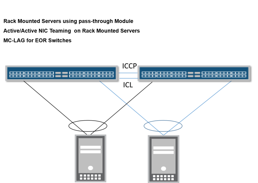
In this blog , we will discuss how traditional model of network switches placement (End of Row) can be coupled with blade chassis with different options available for end to end connectivity / high availability.
Network Switches are placed in End of Row and in order to remove STP Multi-Chassis Link Aggregation (MC-LAG) is deployed. Please see one of my earlier blog for understanding of MC-LAG.
Option 1: Rack mounted servers for computing machines, servers have installed multiple NICs in Pass-Though module and Virtual Machines hosted inside servers require Active/Active NIC Teaming.
Option 2 : Blade Chassis has multiple blade servers and each blade servers has more than 1 NIC (which are connected with blade chassis switches through internal fabric link). Virtul Machines hosted inside blade servers require active/active NIC teaming.

Option 3 : Blade Chassis Continue reading
The objective of this blog is to discuss end to end packet (client to server) traversing through a service provider network with special consideration on performance effecting factors.
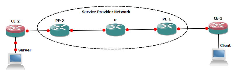
We will suppose client needs to access any of the service hosted in server connected with CE-2, all the network links and NICs on end system are Ethernet based. Almost all the vendors compute machines (PC/ servers) are generating IP data gram with 1500 bytes size (20 bytes header +1480 data bytes) in normal circumstances.
Fragmentation:- If any of link is unable to handle 1500 size IP data-gram then packet will be fragmented and forwarded to its destination where it will be re-assembled. The fragmentation and re-assembly will introduce overhead and defiantly over all performance will be degraded. In IP header following fields are important to detect fragmentation and to re-assemble the packets.
With below Continue reading
MTU is most important aspect for proper functionality of any application. In this blog post I will highlight MTU handling by Junos based devices for (802.3 un-tag and 802.1Q tag packets) .

Simple 802.3 packet header is shown above total packet size is 1514 bytes (14 bytes header + 1500 bytes max payload). Now we will see how Junos based devices handle MTU on access ports.
Link-level type: Ethernet, MTU: 1514, MRU: 0, Link-mode: Auto, Speed: Auto, BPDU Error: None, MAC-REWRITE Error: None, Loopback: Disabled, Source filtering: Disabled, Flow control: Disabled, Auto-negotiation: Disabled,
———-output omitted for brevity——————–
Protocol eth-switch, MTU: 1514
The objective of this article is to highlight design consideration for NIC Teaming between Juniper QFX 5100 (Virtual Chassis -VC) and VMWare ESXI host.
Reference topology is as under:-

We have 2 x Juniper QFX 5100 48S switches which are deployed as VC in order to provide connectivity to compute machines. All compute machines are running VMWare ESXI Hyper-visor. Link Aggregation Group (LAG or Active/ Active NIC Teaming) is required between compute machines and QFX 5100 VC.
Hence,the requirement is to configure LAG (Active/ Active NIC Teaming) between compute machines and network switch for optimal link utilization in addition to fault tolerance if in case one physical link goes down between network switch and compute machine.
In order to achieve the required results one’s needs to understand default load balancing mechanism over LAG member interfaces in Juniper devices and same load balancing mechanism must be configured on VMware ESXI Continue reading
Service Providers networks are always have complex requirements of multi-tenancy, routing & security and pose challenges to network architects. In this blog I will write about SRX integration in Svc Provider Network while highlighting methodologies how to handle challenges of implementing security features with multi-tenancy and routing consideration.
REFERENCE TOPOLOGY
Devices have been classified into following segments based on their role:-
Traffic flow and security requirements are as under:-
In my earlier blog (Junos High Availability Design Guide) it was discussed how to make use of redundant routing engines by configuring features like (GRES, NSR, NSB) for reduction of downtime to minimum possible level.
The real problem is that one RE is active at one time and all PFEs must be connected with active RE . In case of failure of primary Routing Engine (RE) the backup RE will take over and all PFEs now, needs to connect to new primary RE. This scenario can cause momentary disruption of services.
MC-LAG (Active-Active) is correct solution to above described problem as it offers 2 active REs in 2 different devices/ chassis. Important concepts for MC-LAG proper configuration / functionality are as under:-
High availability is one of the important consideration during network design and deployment stage and all most all the network vendors support various high availability features.
The objective of this article is to describe Junos best practices required to achieve minimum downtime in case of fail-over scenarios.
The Routing Engine or Control Plan is the brain in Junos based devices to run and execute all the management functions. Most of the Junos based devices offers redundant routing engines (either through default configuration or through explicit configuration virtual chassis ). At one time only one Routing engine can be active (exception of Active-Active MC-LAG which is beyond the scope of this blog). The mere presence of 2nd routing engine in the Junos device will not add any advantage with respect to high availability until certain features are not configured.


GRES can be configured by following configuration command:-
set chassis redundancy graceful-switchover
Effects of Continue reading