WISP Design – Migrating from Bridged to Routed
TFW adding the 301st subscriber to your bridged WISP….
Why are bridged networks so popular?
- Getting an ISP network started can be a daunting task. Especially, if you don’t have a networking background.
- Understanding L1/L2/L3 is not easy – I spent a number of years working in IT before I really started to grasp concepts like subnetting, the OSI model and Layer 2 vs. Layer 3. It takes a while.
- Bridged networks are very attractive when first starting out. No subnetting is required and the entire network can be NATted out an upstream router with minimal configuration.
What does a “bridged” network look like?
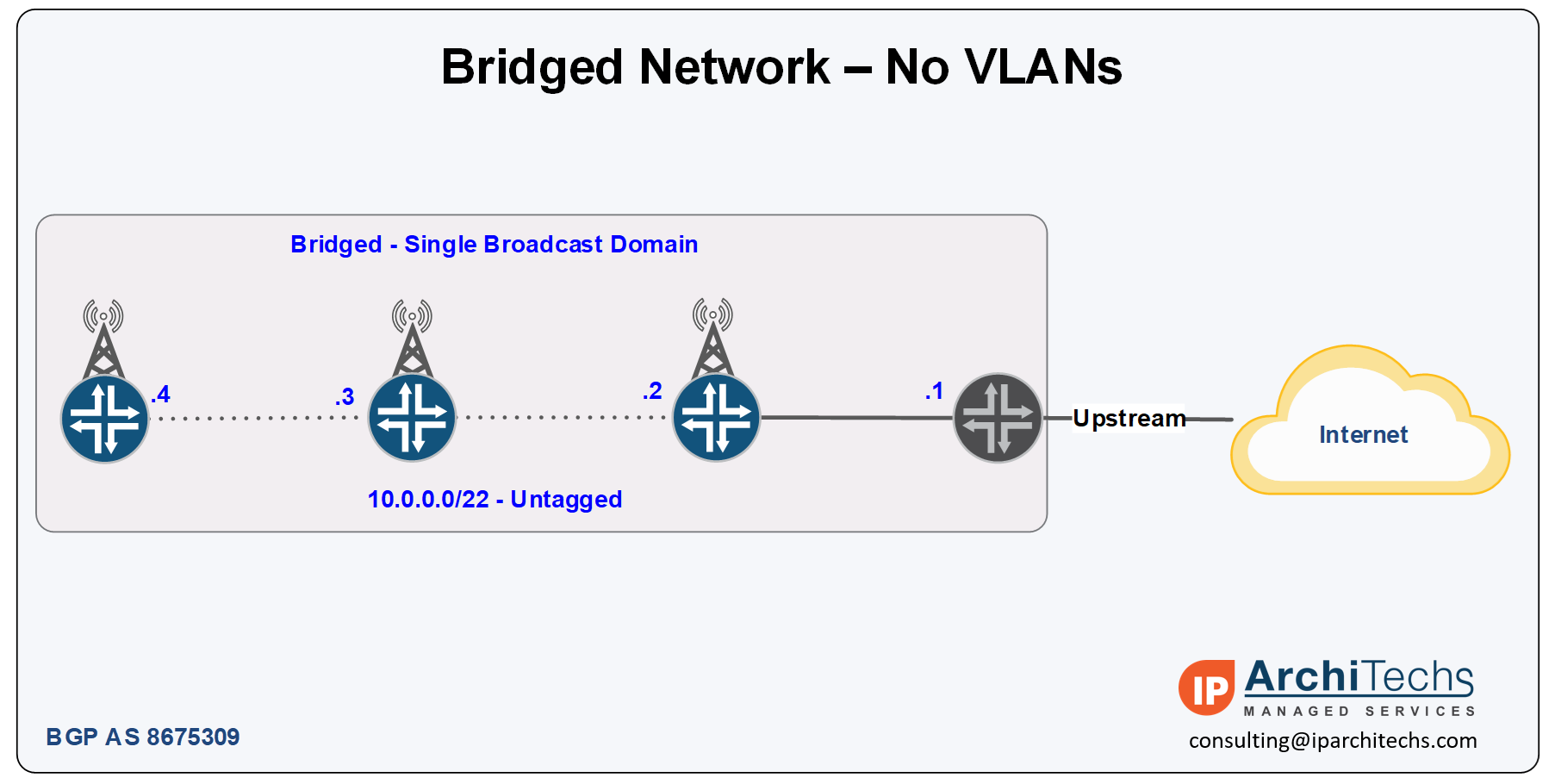
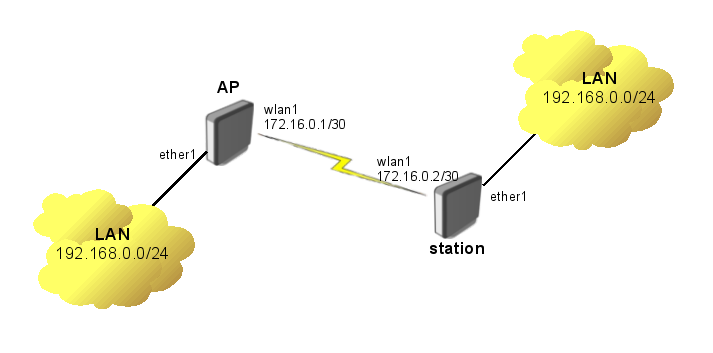
- Bridged networks use a single Layer 3 subnet across the same Layer 2 broadcast domain (typically over switches and software/hardware bridges) which is extended to all towers in the WISP
- Bridging can be done with or without VLANs but they are most commonly untagged.
- The diagram below is a very common example of a bridged WISP network.
What is the difference between switching and bridging?
These days, there isn’t much difference between the two terms, switch is a marketing term for a multiport hardware-accelerated bridge that became popular in the 1990s to Continue reading
Cisco to MikroTik – Switching and VLANs
About the Cisco to MikroTik series
One of the most difficult configuration challenges for MikroTik equipment seems to be switching and VLANs in the CRS series. Admittedly, the revamp of VLAN configuration for MikroTik CRS switches in early 2018 made things a lot easier. But, sometimes there is still confusion on how to configure VLANs and IP addresses in VLANs with MikroTik RouterOS operating on a switch.
This will only cover VLAN configuration for CRS 3xx series switches in RouterOS as SwitchOS is not nearly as common in operational deployments.
CRS 1xx/2xx series use an older style of configuration and seem to be on the way out so I’m not 100% sure whether or not i’ll write a similar guide on that series.
If you’ve been in networking for a while, you probably started with learning the Cisco CLI. Therefore, it is helpful to compare the commands if you want to implement a network with a MikroTik and Cisco switches.
This is the fourth post in a series that creates a Rosetta stone between IOS and RouterOS. Here are some of the others:
Click here for the first article in this series – “Cisco to MikroTik BGP command translation”
Click Continue reading
WISP Design – An overview of adding IPv6 to your WISP
The challenge of adding IPv6 to your WISP
IPv6 is one of those technologies that can feel pretty overwhelming, but it doesn’t have to be. Many of the same ideas and concepts learned in IPv4 networking still apply.
This guide is meant to give you an overview of an example IPv6 addressing plan for an entire WISP as well as the config needed in MikroTik to deploy IPv6 from a core router all the way to a subscriber device.
Benefits of adding IPv6
- Public addressing for all subscribers – reduced need for NAT
- Regulatory compliance – public addressing that is persistent makes it much easier to be compliant for things like CALEA
- Reduced complaints from gamers – Xbox and Playstation both have IPv6 networks and prefer IPv6. This reduces complaints from customers who have gaming consoles that have detected an “improper” NAT configuration.
- Increased security – IPv6, while not impervious to security threats makes it much harder for attackers to scan IPs due to the sheer size of the IP space. If using privacy extensions with SLAAC, it also makes it much harder to target someone online as the IP address seen on the internet changes randomly.
- Improved real Continue reading
MikroTik ISP Design: Building an 802.1q trunk between sites using VPLS and S-tag
Use Case
ISPs that use MikroTik are always looking for new ways to deliver services to customers and expand their offerings. Delivering Layer 2 at scale for customers is a design challenge that comes up frequently.
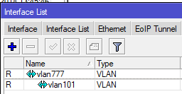
While it’s easy enough to build a VLAN nested inside of another VLAN (see below), this requires you to build all of the VLANs a customer wants to use into the PE router or handoff switch.
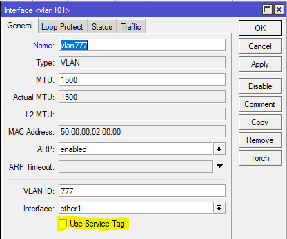
However, if you have a client that needs a layer 2 service delivered to two or more points and wants to be able to treat it just like an 802.1q trunk and add VLANs in an ad-hoc way, then using the S-Tag feature in RouterOS along with VPLS transport is a great option.
What’s the S-tag do???
Clients will often ask me “what’s the S-Tag check box for?”
So a little background on this, there is a protocol for using outer and inner VLAN tags specified in IEEE 802.1ad that uses Service Tag (or S-Tag) to denote the outer VLAN tag used to transport Customer Tags (or C-Tags).
What makes the S-Tag/C-Tag a little bit different is that it actually changes the ethertype of the Frame.
| Continue reading |
|---|
The one thing private equity firms typically overlook when funding startup WISPs…professional network engineers.
.
Funding a new WISP
There are a number of ways to fund a startup Wireless Internet Service Provider (WISP), but the two we most commonly see as network engineering consultants at IP ArchiTechs are self funded by individuals/partners or by leveraging private equity (PE) money.
Private equity has become increasingly popular in the last few years if we are to use our consulting clients as a basis for comparison.
It’s not hard to see why, while you can (and many do) start a WISP on a shoestring budget, getting a significant chunk of initial funding to cover the costs of tower construction/leasing, network equipment, sales/marketing, etc is very attractive as it allows a WISP to build a network that might otherwise take several years of organic growth to achieve.
Network Engineering – the missing ingredient
Many startup WISPs are often borne out of necessity – fast, reliable or economical Internet access – one or more of these is missing in the areas we see WISPs develop.
Typically the stakeholders come from a variety of backgrounds some of which are technical and some aren’t – all of them, however, share a vision of building out Internet access and solving problems Continue reading
ISP Design – Building production MPLS networks with IP Infusion’s OcNOS.
Moving away from incumbent network vendors
One of the challenges service providers have faced in the last decade is lowering the cost per port or per MB while maintaining the same level of availability and service level.
And then add to that the constant pressure from subscribers to increase capacity and meet the rising demand for realtime content.
This can be an especially daunting task when routers with the feature sets ISPs need cost an absolute fortune – especially as new port speeds are released.
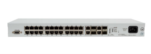
Whitebox, also called disaggregated networking, has started changing the rules of the game. ISPs are working to figure out how to integrate and move to production on disaggregated models to lower the cost of investing in higher speeds and feeds.
Whitebox often faces the perception problem of being more difficult to implement than traditional vendors – which is exactly why I wanted to highlight some of the work we’ve been doing at iparchitechs.com integrating whitebox into production ISP networks using IP Infusion’s OcNOS.
Things are really starting to heat up in the disaggregagted network space after the announcement by Amazon a few days ago that it intends to build and sell whitebox Continue reading
ISP Design – Building production MPLS networks with IP Infusion’s OcNOS.
Moving away from incumbent network vendors
One of the challenges service providers have faced in the last decade is lowering the cost per port or per MB while maintaining the same level of availability and service level.
And then add to that the constant pressure from subscribers to increase capacity and meet the rising demand for realtime content.
This can be an especially daunting task when routers with the feature sets ISPs need cost an absolute fortune – especially as new port speeds are released.

Whitebox, also called disaggregated networking, has started changing the rules of the game. ISPs are working to figure out how to integrate and move to production on disaggregated models to lower the cost of investing in higher speeds and feeds.
Whitebox often faces the perception problem of being more difficult to implement than traditional vendors – which is exactly why I wanted to highlight some of the work we’ve been doing at iparchitechs.com integrating whitebox into production ISP networks using IP Infusion’s OcNOS.
Things are really starting to heat up in the disaggregagted network space after the announcement by Amazon a few days ago that it intends to build and sell whitebox Continue reading
StubArea51.net has a whitebox/disaggregated networking Facebook group!
We have a Facebook group!
If you’re into whitebox, disaggregated or commodity networking, come join the StubArea51.net Facebook group!
All network geeks are welcome 
|
||||||||
StubArea51.net has a whitebox/disaggregated networking Facebook group!
We have a Facebook group!
If you’re into whitebox, disaggregated or commodity networking, come join the StubArea51.net Facebook group!
All network geeks are welcome 
|
||||||||
WISP Design – OSPF “Leapfrog” path for traffic engineering
Introduction
One challenge that every WISP owner or operator has faced is how to leverage unused bandwidth on a backup path to generate more revenue.
For networks that have migrated to MPLS and BGP, this is an easier problem to solve as there are tools that can be used in those protocols like communities or MPLS TE to help manage traffic and set policy.
However, many WISPs rely solely on OSPF and cost adjustment to attempt to influence traffic. Alternatively, trying to use policy routing can lead to a design that doesn’t failover or scale well.
Creating a bottleneck on a single path
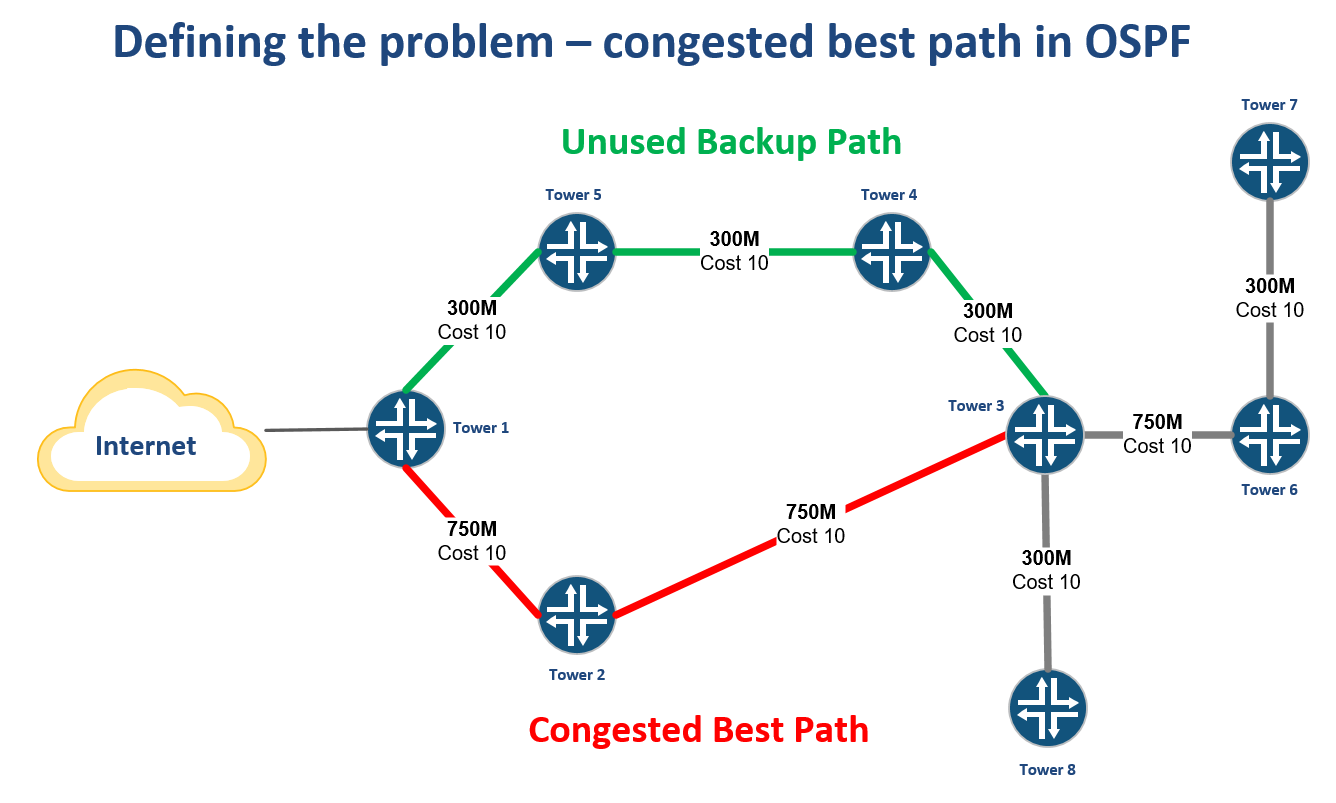
WISPs that are OSPF routed will often have a primary path back to the Internet at one or more points in the network typically from a tower that aggregates multiple backhauls.
As more towers are added that rely on this path, it can create a bottleneck while other paths are unused.
Creating an alternate best path by leapfrogging another router
One way to solve this problem is to use VLANs to create another subnet for OSPF to form an adjacency.
By tagging the VLAN from Tower 6 through Tower 3 and into Tower 4, a new path Continue reading
Cisco to MikroTik – MPLS
About the Cisco to MikroTik series
One of the hardest things to do quickly in network engineering, is learn a new syntax for a NOS. Especially if you have a tight deadline and need to stand up equipment you’ve never worked with before. The command structure for RouterOS can be cumbersome if you are used to the Cisco CLI.
If you’ve been in networking for a while, you probably started with learning the Cisco CLI. Therefore, it is helpful to compare the commands if you want to implement a network with a MikroTik and Cisco routers.
This is the third post in a series that creates a Rosetta stone between IOS and RouterOS. We plan to tackle other command comparisons like VLANs, QoS and basic operations to make it easier for network engineers trained in Cisco IOS to successfully implement Mikrotik / RouterOS devices.
Click here for the first article in this series – “Cisco to MikroTik BGP command translation”
Click here for the second article in this series – “Cisco to MikroTik OSPF command translation”
While many commands have almost the exact same information, others are as close as possible. Since there isn’t always an exact match, sometimes you may have to run Continue reading
PPPoE High Availability Design – Incorporating Multiple Access Concentrators/BRAS
Background:
One of the most widely used protocols for authentication of user connections is PPPoE (or Point-to-Point over Ethernet). Traditionally, PPPoE was used in DSL deployments but became one of the most adopted forms of customer device authentication in many networks. Often used with a AAA system such as RADIUS, the ability to authenticate, authorize and account for customer connections made the use of PPPoE so appealing.
The protocol itself resides at the data link layer (OSI Layer 2) and provides control mechanisms between the connection endpoints. Within this process lies several other moving parts, if you would like to read more you can visit this wiki page which explains PPPoE rather well (https://en.wikipedia.org/wiki/Point-to-Point_Protocol_over_Ethernet ). For the purpose of this article though, I will be sticking to a very specific problem that arises; how to build redundancy when using PPPoE.
PPPoE is a layer 2 connection protocol widely used in service provider networks. Connections initiated from a client terminate on what is known as a BRAS (Broadband Remote Authentication Server), or Access Concentrator (AC) from herein. The function of the AC is to negotiate the link parameters between itself and the client and Continue reading
WISP Design – Building Highly Available VPLS for Public Subnets
What is VPLS?
Virtual Private LAN Service or VPLS is a Layer 2 overlay or tunnel that allows for the encapsulation of ethernet frames (with or without VLAN tags) over an MPLS network.
https://tools.ietf.org/html/rfc4762
VPLS is often found in Telco networks that rely on PPPoE to create centralized BRAS deployments by bringing all of the end users to a common point via L2.
MikroTik VPLS example (https://wiki.mikrotik.com/wiki/Transparently_Bridge_two_Networks_using_MPLS)
Background
The idea for this post came out of a working session (at the bar of course) at WISPAmerica 2018 in Birmingham, Alabama.
There was a discussion about how to create redundancy for VPLS tunnels on multiple routers. I started working on this in EVE-NG as we were talking about it.
The goal is creating highly available endpoints for VPLS when using them to deploy a public subnet that can be delivered to any tower in the WISP. The same idea works for wireline networks as well.
Use Case
As IPv4 becomes harder to get, ISPs like WISPs, without large blocks of public space find it difficult to deploy them in smaller subnets. The idea behind breaking up a /23 or /24 for example, is that every Continue reading


