AI for Network Engineers: Recurrent Neural Network (RNN)
Introduction
So far, this book has introduced two neural network architectures. The first one, the Feed-Forward Neural Network (FNN), works well for simple tasks, such as recognizing handwritten digits in small-sized images. The second one, the Convolutional Neural Network (CNN), is designed for processing larger images. CNNs can identify objects in images even when the location or orientation of the object changes.
This chapter introduces the Recurrent Neural Network (RNN). Unlike FNNs and CNNs, an RNN’s inputs include not only the current data but also all the inputs it has processed previously. In other words, an RNN preserves and uses historical data. This is achieved by feeding the output of the previous time step back into the hidden layer along with the current input vector.
Although RNNs can be used for predicting sequential data of variable lengths, such as sales figures or a patient’s historical health records, this chapter focuses on how RNNs can perform character-based text autocompletion. The upcoming chapters will explore word-based text prediction.
Text Datasets
For training the RNN model, we typically use text datasets like IMDB Reviews or the Wikipedia Text Corpus. However, in this chapter, we simplify the process by using a tailored dataset containing Continue reading
AI for Network Engineers: Convolutional Neural Network
Introduction
The previous chapter explained how Feed-forward Neural Networks (FNNs) can be used for multi-class classification of 28 x 28 pixel handwritten digits from the MNIST dataset. While FNNs work well for this type of task, they have significant limitations when dealing with larger, high-resolution color images.
In neural network terminology, each RGB value of an image is treated as an input feature. For instance, a high-resolution 600 dpi RGB color image with dimensions 3.937 x 3.937 inches contains approximately 5.58 million pixels, resulting in roughly 17 million RGB values.
If we use a fully connected FNN for training, all these 17 million input values are fed into every neuron in the first hidden layer. Each neuron must compute a weighted sum based on these 17 million inputs. The memory required for storing the weights depends on the numerical precision format used. For example, using the 16-bit floating-point (FP16) format, each weight requires 2 bytes. Thus, the memory requirement per neuron would be approximately 32 MB. If the first hidden layer has 10,000 neurons, the total memory required for storing the weights in this layer would be around 316 GB.
In contrast, Convolutional Neural Networks (CNNs) use Continue reading
AI for Network Engineers: Multi-Class Classification
Introduction
This chapter explains the multi-class classification training process. It begins with an introduction to the MNIST dataset (Modified National Institute of Standards and Technology dataset). Next, it describes how the SoftMax activation function computes the probability of the image fed into the model during the forward pass and how the weight parameters are adjusted during the backward pass to improve training results. Additionally, the chapter discusses the data parallelization strategy from a network perspective.
MINST Dataset
We will use the MNIST dataset [1], which consists of handwritten digits, to demonstrate the training process. The MNIST dataset includes four files: (1) a training set with 60,000 gray-scale images (28x28 pixels) and their respective (2) labels, and a test set with 10,000 images (28x28 pixels) and their respective labels. Figure 3-1 illustrates the structure and dependencies between the test dataset and the labels.
The file train-images-idx3-ubyte contains metadata describing how the images are ordered, along with the image pixel order. The file train-labels-idx1-ubyte defines which label (the digits 0-9) corresponds to which image in the image file. Since we have ten possible outputs, we use ten output neurons.
Before the training process begins, the labels for each image-label pair are one-hot Continue reading
AI for Network Engineers: Backpropagation Algorithm
Introduction
This chapter introduces the training model of a neural network based on the Backpropagation algorithm. The goal is to provide a clear and solid understanding of the process without delving deeply into the mathematical formulas, while still explaining the fundamental operations of the involved functions. The chapter also briefly explains why, and in which phases the training job generates traffic to the network, and why lossless packet transport is required. The Backpropagation algorithm is composed of two phases: the Forward pass (computation phase) and the Backward pass (adjustment and communication phase).
In the Forward pass, neurons in the first hidden layer calculate the weighted sum of input parameters received from the input layer, which is then passed to the neuron's activation function. Note that neurons in the input layer are not computational units; they simply pass the input variables to the connected neurons in the first hidden layer. The output from the activation function of a neuron is then used as input for the connected neurons in the next layer. The result of the activation function in the output layer represents the model's prediction, which is compared to the expected value (ground truth) using the error function. The output Continue reading
AI for Network Engineers: Chapter 2 – Backpropagation Algorithm: Introduction
This chapter introduces the training model of a neural network based on the Backpropagation algorithm. The goal is to provide a clear and solid understanding of the process without delving deeply into the mathematical formulas, while still explaining the fundamental operations of the involved functions. The chapter also briefly explains why, and in which phases the training job generates traffic to the network, and why lossless packet transport is required. The Backpropagation algorithm is composed of two phases: the Forward pass (computation phase) and the Backward pass (adjustment and communication phase).
In the Forward pass, neurons in the first hidden layer calculate the weighted sum of input parameters received from the input layer, which is then passed to the neuron's activation function. Note that neurons in the input layer are not computational units; they simply pass the input variables to the connected neurons in the first hidden layer. The output from the activation function of a neuron is then used as input for the connected neurons in the next layer, whether it is another hidden layer or the output layer. The result of the activation function in the output layer represents the model's prediction, which is compared to the expected Continue reading
Artificial Intelligence for Network Engineers: Introduction
Several books on artificial intelligence (AI) and deep learning (DL) have been published over the past decade. However, I have yet to find a book that explains deep learning from a networking perspective while providing a solid introduction to DL. My goal is to fill this gap by writing a book titled AI for Network Engineers (note that the title name may change during the writing process). Writing about such a complex subject will take time, but I hope to complete and release it within a year.
Part I: Deep Learning and Deep Neural Networks
The first part of the book covers the theory behind Deep Learning. It begins by explaining the construct of a single artificial neuron and its functionality. Then, it explores various Deep Neural Network models, such as Feedforward Neural Networks (FNN), Convolutional Neural Networks (CNN), and Recurrent Neural Networks (RNN). Next, the first part discusses data and model parallelization strategies such as Data, Pipeline, and Tensor Parallelism, explaining how input data and/or model sizes that exceed the memory capacity of GPUs within a single server can be distributed across multiple GPU servers.
Part II: AI Data Center Networking - Lossless Ethernet
After a brief Continue reading
AI for Network Engineers: Chapter 1 – Deep Learning Basics
Content
Introduction
Artificial Neuron
Weighted Sum for Pre-Activation Value
ReLU Activation Function for Post-Activation
Bias Term
S-Shaped Functions – TANH and SIGMOID
Network Impact
Summary
References
Artificial Neuron
Weighted Sum for Pre-Activation Value
ReLU Activation Function for Post-Activation
Bias Term
S-Shaped Functions – TANH and SIGMOID
Network Impact
Summary
References
Introduction
Artificial Intelligence (AI) is a broad term for solutions that aim to mimic the functions of the human brain. Machine Learning (ML), in turn, is a subset of AI, suitable for tasks like simple pattern recognition and prediction. Deep Learning (DL), the focus of this section, is a subset of ML that leverages algorithms to extract meaningful patterns from data. Unlike ML, DL does not necessarily require human intervention, such as providing structured, labeled datasets (e.g., 1,000 bird images labeled as “bird” and 1,000 cat images labeled as “cat”).
DL utilizes layered, hierarchical Deep Neural Networks (DNNs), where hidden and output layers consist of computational units, artificial neurons, which individually process input data. The nodes in the input layer pass the input data to the first hidden layer without performing any computations, which is why they are not considered neurons or computational units. Each neuron calculates a pre-activation value (z) based on the input received from the previous layer and then applies an activation function to this value, producing a post-activation output (ŷ) value. There are various DNN models, such as Feed-Forward Neural Networks (FNN), Convolutional Neural Networks (CNN), and Recurrent Neural Networks (RNN), each designed for different use cases. For example, FNNs are suitable for simple, structured tasks like handwritten digit recognition using the MNIST dataset [1], CNNs are effective for larger image recognition tasks such as with the CIFAR-10 dataset [2], and RNNs are commonly used for time-series forecasting, like predicting future sales based on historical sales data.
To provide accurate predictions based on input data, neural networks are trained using labeled datasets. The MNIST (Modified National Institute of Standards and Technology) dataset [1] contains 60,000 training and 10,000 test images of handwritten digits (grayscale, 28x28 pixels). The CIFAR-10 [2] dataset consists of 60,000 color images (32x32 pixels), with 50,000 training images and 10,000 test images, divided into 10 classes. The CIFAR-100 dataset [3], as the name implies, has 100 image classes, with each class containing 600 images (500 training and 100 test images per class). Once the test results reach the desired level, the neural network can be deployed to production.
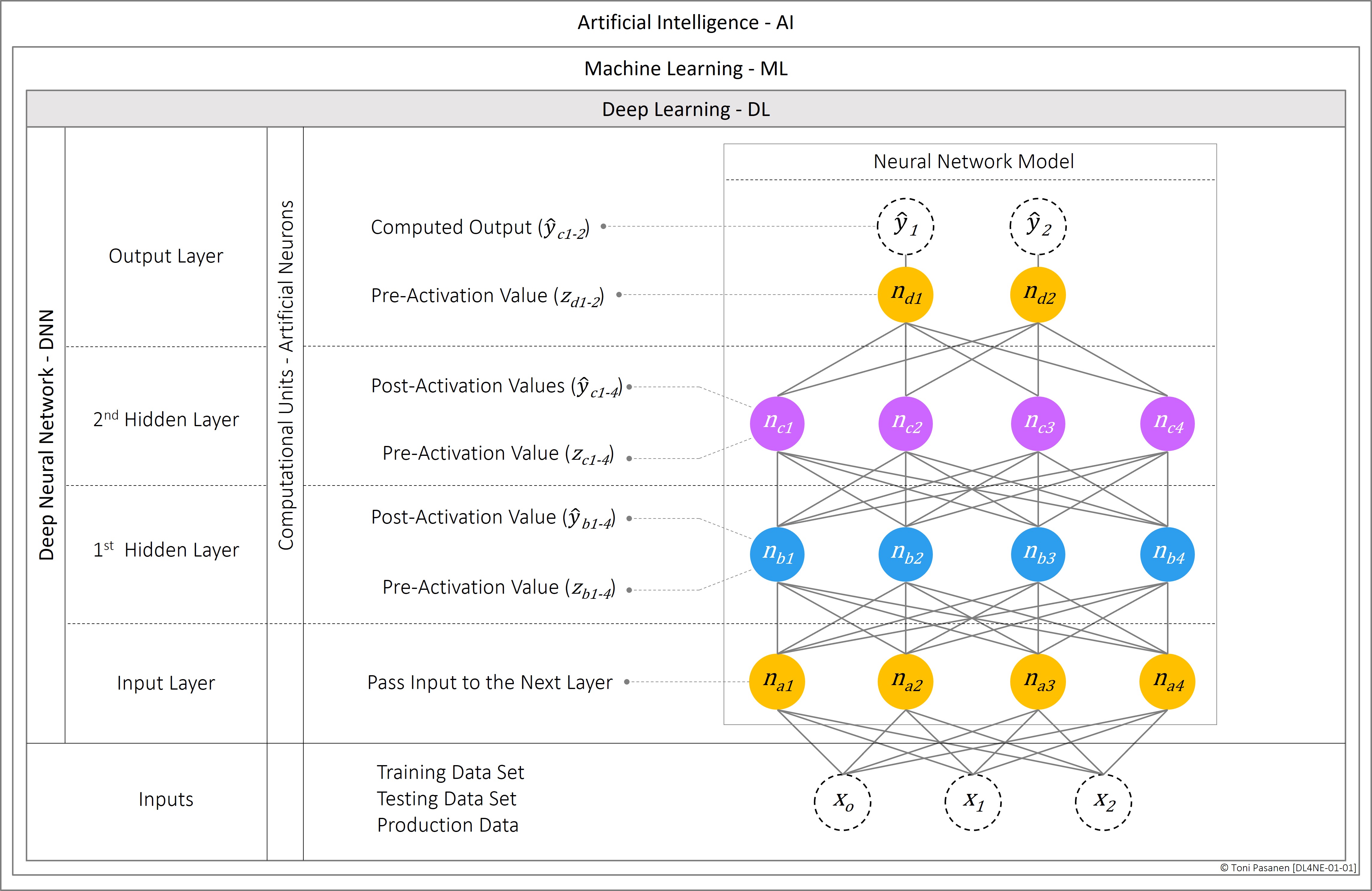
Figure 1-1: Deep Learning Introduction.
AI/ML Networking: Part-IV: Convolutional Neural Network (CNN) Introduction
Feed-forward Neural Networks are suitable for simple tasks like basic time series prediction without long-term relationships. However, FNNs is not a one-size-fits-all solution. For instance, digital image training process uses pixel values of image as input data. Consider training a model to recognize a high resolution (600 dpi), 3.937 x 3.937 inches digital RGB (red, green, blue) image. The number of input parameters can be calculated as follows:
Width: 3.937 in x 600 ≈ 2362 pixels
Height: 3.937 in x 600 ≈ 2362 pixels
Pixels in image: 2362 x 2362 = 5,579,044 pixels
RGB (3 channels): 5,579,044 pxls x 3 channels = 16 737 132
Total input parameters: 16 737 132
Memory consumption: ≈ 16 MB
FNNs are not ideal for digital image training. If we use FNN for training in our example, we fed 16,737,132 input parameters to the first hidden layer, each having unique weight. For image training, there might be thousands of images, handling millions of parameters demands significant computation cycles and is a memory-intensive process. Besides, FNNs treat each pixel as an independent unit. Therefore, FNN algorithm does not understand dependencies between pixels and cannot recognize the same image if it shifts within the frame. Besides, FNN does not detect edges and other crucial details.
A better model for training digital images is Convolutional Neural Networks (CNNs). Unlike in FFN neural networks where each neuron has a unique set of weights, CNNs use the same set of weights (Kernel/Filter) across different regions of the image, which reduces the number of parameters. Besides, CNN algorithm understands the pixel dependencies and can recognize patterns and objects regardless of their position in the image.
The input data processing in CNNs is hierarchical. The first layer, convolutional layers, focuses on low-level features such as textures and edges. The second layer, pooling layer, captures higher-level features like shapes and objects. These two layers significantly reduce the input data parameters before they are fed into the neurons in the first hidden layer, the fully connected layer, where each neuron has unique weights (like FNNs).

AI/ML Networking: Part-III: Basics of Neural Networks Training Process
Neural Network Architecture Overview
Deep Neural Networks (DNN) leverage various architectures for training, with one of the simplest and most fundamental being the Feedforward Neural Network (FNN). Figure 2-1 illustrates our simple, three-layer FNN.
Input Layer:
The first layer doesn’t have neurons, instead the input data parameters X1, X2, and X3 are in this layer, from where they are fed to first hidden layer.
Hidden Layer:
The neurons in the hidden layer calculate a weighted sum of the input data, which is then passed through an activation function. In our example, we are using the Rectified Linear Unit (ReLU) activation function. These calculations produce activation values for neurons. The activation value is modified input data value received from the input layer and published to upper layer.
Output Layer:
Neurons in this layer calculate the weighted sum in the same manner as neurons in the hidden layer, but the result of the activation function is the final output.
The process described above is known as the Forwarding pass operation. Once the forward pass process is completed, the result is passed through a loss function, where the received value is compared to the expected value. The difference between these two values Continue reading
AI/ML Networking: Part-II: Introduction of Deep Neural Networks
Machine Learning (ML) is a subset of Artificial Intelligence (AI). ML is based on algorithms that allow learning, predicting, and making decisions based on data rather than pre-programmed tasks. ML leverages Deep Neural Networks (DNNs), which have multiple layers, each consisting of neurons that process information from sub-layers as part of the training process. Large Language Models (LLMs), such as OpenAI’s GPT (Generative Pre-trained Transformers), utilize ML and Deep Neural Networks.
For network engineers, it is crucial to understand the fundamental operations and communication models used in ML training processes. To emphasize the importance of this, I quote the Chinese philosopher and strategist Sun Tzu, who lived around 600 BCE, from his work The Art of War.
If you know the enemy and know yourself, you need not fear the result of a hundred battles.
We don’t have to be data scientists to design a network for AI/ML, but we must understand the operational fundamentals and communication patterns of ML. Additionally, we must have a deep understanding of network solutions and technologies to build a lossless and cost-effective network for enabling efficient training processes.
In the upcoming two posts, I will explain the basics of:
a) Data Models: Continue reading
AI/ML Networking Part I: RDMA Basics
Remote Direct Memory Access - RDMA Basics
Introduction
Remote Direct Memory Access (RDMA) architecture enables efficient data transfer between Compute Nodes (CN) in a High-Performance Computing (HPC) environment. RDMA over Converged Ethernet version 2 (RoCEv2) utilizes a routed IP Fabric as a transport network for RDMA messages. Due to the nature of RDMA packet flow, the transport network must provide lossless, low-latency packet transmission. The RoCEv2 solution uses UDP in the transport layer, which does not handle packet losses caused by network congestion (buffer overflow on switches or on a receiving Compute Node). To avoid buffer overflow issues, Priority Flow Control (PFC) and Explicit Congestion Notification (ECN) are used as signaling mechanisms to react to buffer threshold violations by requesting a lower packet transfer rate.
Before moving to RDMA processes, let’s take a brief look at our example Compute Nodes. Figure 1-1 illustrates our example Compute Nodes (CN). Both Client and Server CNs are equipped with one Graphical Processing Unit (GPU). The GPU has a Network Interface Card (NIC) with one interface. Additionally, the GPU has Device Memory Units to which it has a direct connection, bypassing the CPU. In real life, a CN may have several GPUs, each with multiple memory units. Intra-GPU communication within the CN happens over high-speed NVLinks. The connection to remote CNs occurs over the NIC, which has at least one high-speed uplink port/interface.
Figure 1-1 also shows the basic idea of a stacked Fine-Grained 3D DRAM (FG-DRAM) solution. In our example, there are four vertically interconnected DRAM dies, each divided into eight Banks. Each Bank contains four memory arrays, each consisting of rows and columns that contain memory units (transistors whose charge indicates whether a bit is set to 1 or 0). FG-DRAM enables cross-DRAM grouping into Ranks, increasing memory capacity and bandwidth.
The upcoming sections introduce the required processes and operations when the Client Compute Node wants to write data from its device memory to the Server Compute Node’s device memory. I will discuss the design models and requirements for lossless IP Fabric in later chapters.

Figure 1-1: Fine-Grained DRAM High-Level Architecture.
Continue reading
BGP EVPN Fabric – Remote Leaf MAC Learning Process
Remote VTEP Leaf-102: Low-Level Control Plane Analysis
In this section, we will first examine the update process of the BGP tables on the VTEP switch Leaf-102 when it receives a BGP Update message from Spine-11. After that, we will go through the update processes for the MAC-VRF and the MAC Address Table. Finally, we will examine how the VXLAN manager on Leaf-102 learns the IP address of Leaf-10's NVE interface and creates a unidirectional NVE peer record in the NVE Peer Database based on this information.
Remote Learning: BGP Processes
We have configured switches Leaf-101 and Leaf-102 as Route Reflector Clients on the Spine-11 switch. Spine-11 has stored the content of the BGP Update message sent by Leaf-101 in the neighbor-specific Adj-RIB-In of Leaf-101. Spine-11 does not import this information in its local BGP Loc-RIB because we have not defined a BGP import policy. Since Leaf-102 is an RR Client, the BGP process on Spine-11 copies this information in the neighbor-specific Adj-RIB-Out table for Leaf-102 and sends the information to Leaf-102 in a BGP Update message. The BGP process on Leaf-102 stores the received information from the Adj-RIB-In table to the BGP Loc-RIB according to the import policy of EVPN Instance 10010 (import RT 65000:10010). During the import process, the Route Distinguisher values are also modified to match the configuration of Leaf-102: change the RD value from 192.168.10.101:32777 (received RD) to 192.168.10.102:32777 (local RD).

Figure 3-13: MAC Address Propagation Process – From BGP Adj-RIB-Out.
Continue reading
EVPN Instance Deployment Scenario 1: L2-Only EVPN Instance
In this scenario, we are building a protected Broadcast Domain (BD), which we extend to the VXLAN Tunnel Endpoint (VTEP) switches of the EVPN Fabric, Leaf-101 and Leaf-102. Note that the VTEP operates in the Network Virtualization Edge (NVE) role for the VXLAN segment. The term NVE refers to devices that encapsulate data packets to transport them over routed IP infrastructure. Another example of an NVE device is the MPLS Provider Edge (MPLS-PE) router at the edge of the MPLS network, doing MPLS labeling. The term “Tenant System” (TS) refers to a physical host, virtual machine, or an intra-tenant forwarding component attached to one or more Tenant-specific Virtual Networks. Examples of TS forwarding components include firewalls, load balancers, switches, and routers.
We begin by configuring L2 VLAN 10 to Leaf-101 and Leaf-102 and associate it with the vn-segment 10010. From the NVE perspective, this constitutes an L2-Only network segment, meaning we do not configure an Anycast Gateway (AGW) for the segment, and it does not have any VRF association.
Next, we deploy a Layer 2 EVPN Instance (EVI) with VXLAN Network Identifier (VNI) 10010. We utilize the 'auto' option to generate the Route Distinguisher (RD) and the Route Target (RT) import and export values for the EVI. The RD value is derived from the NVE Interface IP address and the VLAN Identifier (VLAN 10) associated with the EVI, added to the base value 32767 (e.g., 192.168.100.101:32777). The use of the VLAN ID as part of the automatically generated RD value is the reason why VLAN is configured before the EVPN Instance. Similarly, the RT values are derived from the BGP ASN and the VNI (e.g., 65000:10010).
As the final step for EVPN Instance deployment, we add EVI 10010 under the NVE interface configuration as a member vni with the Multicast Group 239.1.1.1 we are using for Broadcast, Unknown Unicast, and Multicast (BUM) traffic.
For connecting TS1 and TS2 to the Broadcast domain, we will configure Leaf-101's interface Eth 1/5 and Leaf-102's interface Eth1/3 as access ports for VLAN 10.
A few words regarding the terminology utilized in Figure 3-2. '3-Stage Routed Clos Fabric' denotes both the physical topology of the network and the model for forwarding data packets. The 3-Stage Clos topology has three switches (ingress, spine, and egress) between the attached Tenant Systems. Routed, in turn, means that switches forward packets based on the destination IP address.
With the term VXLAN Segment, I refer to a stretched Broadcast Domain, identified by the VXLAN Network Identifier value defined under the EVPN Instance on Leaf switches.

Figure 3-2: L2-Only Intra VN Connection.
Continue readingDeploying and Analyze EVPN Instances: Deployment Scenarios
In the previous section, we built a Single-AS EVPN Fabric with OSPF-enabled Underlay Unicast routing and PIM-SM for Multicast routing using Any Source Multicast service. In this section, we configure two L2-Only EVPN Instances (L2-EVI) and two L2/L3 EVPN Instances (L2/3-EVI) in the EVPN Fabric. We examine their operations in six scenarios depicted in Figure 3-1.
Scenario 1 (L2-Only EVI, Intra-VN):
In the Deployment section, we configure an L2-Only EVI with a Layer 2 VXLAN Network Identifier (L2VNI) of 10010. The Default Gateway for the VLAN associated with the EVI is a firewall. In the Analyze section, we observe the Control Plane and Data Plane operation when a) connecting Tenant Systems TS1 and TS2 to the segment, and b) TS1 communicates with TS2 (Intra-VN Communication).
Scenario 2 (L2-Only EVI, Inter-VN):
In the Deployment section, we configure another L2-Only EVI with L2VNI 10020, to which we attach TS3 and TS4. In the Analyze section, we examine EVPN Fabric's Control Plane and Data Plane operations when TS2 (L2VNI 10010) sends data to TS3 (L2VNI 10020), Inter-VN Communication.
Scenario 3 (L2/L3 EVI, Intra-VN):
In the Deployment section, we configure a Virtual Routing and Forwarding (VRF) Instance named VRF-NWKT with L3VNI 10077. Next, Continue reading
Configuration of BGP afi/safi L2VPN EVPN and NVE Tunnel Interface
Overlay Network Routing: MP-BGP L2VPN/EVPN
EVPN Fabric Data Plane – MP-BGP
Instead of being a protocol, EVPN is a solution that utilizes the Multi-Protocol Border Gateway Protocol (MP-BGP) for its control plane in an overlay network. Besides, EVPN employs Virtual eXtensible Local Area Network (VXLAN) encapsulation for the data plane of the overlay network.
Multi-Protocol BGP (MP-BGP) is an extension of BGP-4 that allows BGP speakers to encode Network Layer Reachability Information (NLRI) of various address types, including IPv4/6, VPNv4, and MAC addresses, into BGP Update messages. The MP_REACH_NLRI path attribute (PA) carried within MP-BGP update messages includes Address Family Identifier (AFI) and Subsequent Address Family Identifier (SAFI) attributes. The combination of AFI and SAFI determines the semantics of the carried Network Layer Reachability Information (NLRI). For example, AFI-25 (L2VPN) with SAFI-70 (EVPN) defines an MP-BGP-based L2VPN solution, which extends a broadcast domain in a multipoint manner over a routed IPv4 infrastructure using an Ethernet VPN (EVPN) solution.
BGP EVPN Route Types (BGP RT) carried in BGP update messages describe the advertised EVPN NLRIs (Network Layer Reachability Information) type. Besides publishing IP Prefix information with IP Prefix Route (EVPN RT 5), BGP EVPN uses MAC Advertisement Route (EVPN RT 2) Continue reading
Single-AS EVPN Fabric with OSPF Underlay: Underlay Network Multicast Routing: Any-Source Multicast – ASM
Underlay Network Multicast Routing: PIM-SM
In a traditional Layer 2 network, switches forward Intra-VLAN data traffic based on the destination MAC address of Ethernet frames. Therefore, hosts within the same VLAN must resolve each other's MAC-IP address bindings using Address Resolution Protocol (ARP). When a host wants to open a new IP connection with a device in the same subnet and the destination MAC address is unknown, the connection initiator generates an ARP Request message. In the message, the sender provides its own MAC-IP binding information and queries the MAC address of the owner of the target IP. The ARP Request messages are Layer 2 Broadcast messages with the destination MAC address FF:FF:FF:FF:FF:FF.
EVPN Fabric is a routed network and requires a solution for Layer 2 Broadcast messages. We can select either BGP EVPN-based Ingress-Replication (IR) solution or enable Multicast routing in Underlay network. This chapter introduces the latter model. As in previous Unicast Routing section, we follow the Multicast deployment workflow of Nexus Dashboard Fabric Controller (NDFC) graphical user interface.
Figure 2-4 depicts the components needed to deploy Multicast service in the Underlay network. The default option for selecting “RP mode” is ASM (Any-Source Multicast). ASM is Continue reading
Single-AS EVPN Fabric with OSPF Underlay: Underlay Network Unicast Routing
Introduction
Image 2-1 illustrates the components essential for designing a Single-AS, Multicast-enabled OSPF Underlay EVPN Fabric. These components need to be established before constructing the EVPN fabric. I've grouped them into five categories based on their function.
- General: Defines the IP addressing scheme for Spine-Leaf Inter-Switch links, set the BGP AS number and number of BGP Route-Reflectors, and set the MAC address for the Anycast gateway for client-side VLAN routing interfaces.
- Replication: Specifies the replication mode for Broadcast, Unknown Unicast, and Multicast (BUM) traffic generated by Tenant Systems. The options are Ingress-Replication and Multicast (ASM or BiDir options).
- vPC: Describes vPC multihoming settings such as vPC Peer Link VLAN ID and Port-Channel ID, vPC Auto-recovery and Delay Restore timers, and define vPC Peer Keepalive interface.
- Protocol: Defines the numbering schema for Loopback interfaces, set the OSPF Area identifier, and OSPF process name.
- Resources: Reserves IP address ranges for Loopback interfaces defined in the Protocols category and for the Rendezvous Point specified in the Replication category. Besides, in this section, we reserve Layer 2 and Layer 3 VXLAN and VLAN ranges for overlay network segments.
The model presented in Figure 2-1 outlines the steps for configuring an EVPN fabric using the Continue reading
BGP EVPN with VXLAN: Fabric Overview

Figure illustrates the simplified operation model of EVPN Fabric. At the bottom of the figure is four devices, Tenant Systems (TS), connected to the network. When speaking about TS, I am referring to physical or virtual hosts. Besides, The Tenant System can be a forwarding component attached to one or more Tenant-specific Virtual Networks. Examples of TS forwarding components include firewalls, load balancers, switches, and routers.
We have connected TS1 and TS2 to VLAN 10 and TS3-4 to VLAN 20. VLAN 10 is associated with EVPN Instance (EVI) 10010 and VLAN 20 to EVI 10020. Note that VLAN-Id is switch-specific, while EVI is Fabric-wide. Thus, subnet A can have VLAN-Id XX on one Leaf switch and VLAN-Id YY on another. However, we must map both VLAN XX and YY to the same EVPN Instance.
When a TS connected to the Fabric sends the first Ethernet frame, the Leaf switch stores the source MAC address in the MAC address table, where it is copied to the Layer 2 routing table (L2RIB) of the EVPN Instance. Then, the BGP process of the Leaf switch advertises the MAC address with its reachability information to its BGP EVPN peers, essentially the Spine switches. Continue reading
Azure Networking: Cloud Scale Load Balancing
Introduction
During the load balancer deployment process, we define a virtual IP (a.k.a front-end IP) for our published service. As a next step, we create a backend (BE) pool to which we attach Virtual Machines using either their associated vNIC or Direct IP (DIP). Then, we bind the VIP to BE using an Inbound rule. Besides, in this phase, we create and associate health probes with inbound rules for monitoring VM's service availability. If VMs in the backend pool also initiate outbound connections, we build an outbound policy, which states the source Network Address Translation (SNAT) rule (DIP, src port > VIP, src port).
This chapter provides an overview of the components of the Azure load balancer service: Centralized SDN Controller, Virtual Load balancer pools, and Host Agents. In this chapter, we discuss control plane and data plane operation.
Management & Control Plane – External Connections
Figure 20-1 depicts our example diagram. The top-most box, Loadbalancer deployment, shows our LB settings. We intend to forward HTTP traffic from the Internet to VIP 1.2.3.4 to either DIP 10.0.0.4 (vm-beetle) or DIP 10.0.0.5 (vm-bailey). The health probe associated with Continue reading
Adding TS’s IP Address to MAC-VRF (L2RIB) and IP-VRF (L3RIB)
In the previous chapter, we discussed how a VTEP learns the local TS's MAC address and the process through which the MAC address is programmed into BGP tables. An example VTEP device was configured with a Layer 2 VLAN and an EVPN Instance without deploying a VRF Context or VLAN routing interface. This chapter introduces, at a theoretical level, how the VTEP device, besides the TS's MAC address, learns the TS's IP address information after we have configured the VRF Context and routing interface for our example VLAN.

Figure 1-3: MAC-VRF Tenant System’s IP Address Propagation.
I have divided Figure 1-3 into three sections. The section on the top left, Integrated Routing and Bridging - IRB illustrates the components required for intra-tenant routing and their interdependencies. By configuring a Virtual Routing and Forwarding Context (VRF Context), we create a closed routing environment with a per-tenant IP-VRF L3 Routing Information Base (L3RIB). Within the VRF Context, we define the Layer 3 Virtual Network Identifier (L3VNI) along with the Route Distinguisher (RD) and Route Target (RT) values. The RD of the VRF Context enables the use of overlapping IP addresses across different tenants. Based on the RT value of the VRF Context, Continue reading