Route Filtering Techniques : Access-lists, Route-map and Distribution-lists
Back to Basics : Access-Lists and Types
Before we talk about these protocols, I would like to tell you guys that we have our own youtube channel for various network videos that can further help you guys to study further. I will going to add many more videos soon on the channel, Please subscribe to the channel for the study network related videos
Subscribe us on Youtube: http://y2u.be/0c4lMYVp9go
But now if we are talking about all these route filtering protocol, we will take one by one to explain how and what they filter out in the network
IP Access List Route Filtering
So let's talk about the ACL or so called access-lists. An access-list is basically a mechanism accepting certain input from Continue reading
Basic Configuration of OSPF Over non-Broadcast Networks ( NBMA)
Today I will talk about the basic set of configurations of OSPF NBMA network type over the non Broadcast networks. Many of you guys already aware of the NBMA network type in the OSPF network.
Lets have a Basic OSPF Network diagram for you guys, then we will come up with the diagram showing the routers connected in the OSPF via Frame-Relay network which will act as a NBMA OSPF network type.
NBMA stands for Non-Broadcast Multiple Access where the network types X.25 and Frame Relay has no capability to support Broadcast traffic. Here in our example we will take Frame-Relay as a NBMA network which is connected via two routers 1 and 2. I defined these routers as Continue reading
Before we start with the OSFP NBMA configuration part, I would like to tell you guys that we have our own youtube channel for various network videos that can further help you guys to study further. I will going to add many more videos soon on the channel, Please subscribe to the channel for the study network related videos
Subscribe us on Youtube: http://y2u.be/0c4lMYVp9go
Lets have a Basic OSPF Network diagram for you guys, then we will come up with the diagram showing the routers connected in the OSPF via Frame-Relay network which will act as a NBMA OSPF network type.
 |
| Fig 1.1- OSPF Network Connected to other Campus Via NBMA Networks- Frame Relay |
NBMA stands for Non-Broadcast Multiple Access where the network types X.25 and Frame Relay has no capability to support Broadcast traffic. Here in our example we will take Frame-Relay as a NBMA network which is connected via two routers 1 and 2. I defined these routers as Continue reading
Cisco Wireless Solution : Local Mode Vs Flex Connect
Today I will talk about the Wireless deployment modes and will discuss which and why to use that deployment mode in the your wireless network.
Wireless Deployment :Local Mode
Wireless Deployment :Local Mode
In local mode, an AP creates two CAPWAP tunnels to the WLC. One is for management, the other is data traffic. This behaviour is known as "centrally switched" because the data traffic is switched(bridged) from the AP to the controller where it is then routed by some routing device.
Locally switched means the traffic is terminated at the local switch adjacent to the access point.
 |
| Fig 1.1- Local Mode behind Mesh Network |
Its a good idea if you have traffic that the client is sending to the local site rather than it going via the controller and travelling over the WAN link twice say for file or print services
Wireless Deployment : Flex Mode
Flex Connect also known as HREAP by the old timers, allows data traffic to be switched locally and not go back to the controller. It basically causes the AP to behave like an autonomous AP, but be managed by the WLC. In this mode, the AP can still function even Continue reading
Software Defined Networking : Introduction to VeloCloud SD-WAN Solution
Today I am going to talk about the another article on the Software defined networking and that is SD-WAN. SD-WAN stands for the software defined WAN. Earlier i talk about the SD-WAN solution from the Viptela which is now acquired by Cisco systems.
As I earlier talked about the SD-WAN architecture and the main focus on the control, Data and management plane. The intent is to separate the Data and control plane from the devices. Data plane as usual will be there at the box level (Routers, switches) while separated the control plane to centralised management systems where all decisions will be taken care.
For Viptela SD-WAN solution, please go through the below link for further study
Viptela SD-WAN Solution - Cisco Systems Company
I would like to tell you guys that we have our own youtube channel for various network videos that can further help you guys to study further. I will going to add many more videos soon on the channel, Please subscribe to the channel for the study network related videos
Subscribe us on Youtube: http://y2u.be/0c4lMYVp9go
VeloCloud SD-WAN Solution
Let's talk about the VeloCloud SD-WAN solution, as similar to the other vendors, Velocloud uses the same Continue reading
Basics on Security : IPS Vs IDS Vs Firewalls
Today I am going to talk about the another security topic which i will going to highlight the difference between the IPS, IDS and the firewalls in their functionality. Before I will start with the IPS, IDS and Firewalls I would like to tell you guys that we have our own youtube channel for various network videos that can further help you guys to study further. I will going to add many more videos soon on the channel, Please subscribe to the channel for the study network related videos
Subscribe us on Youtube: http://y2u.be/0c4lMYVp9go
Subscribe us on Youtube: http://y2u.be/0c4lMYVp9go
IPS - Intrusion Prevention System
IPS-Intrusion Prevention System inspects traffic flowing through a network and is capable of blocking or otherwise remediating flows that it determines are malicious. Usually uses a combination of traffic and file signatures and heuristic analysis of flows.
In other words, we can say that a device or application that analyzes packet headers and enforces policy based on protocol type, source address, destination address, source port, and/or destination port. Packets that do not match policy are rejected.
 |
| Fig 1.1- IPS in the Network with Firewall |
It also provideds the analysis of low by sitting inline and seeing all traffic during an Continue reading
The concept of RD and RT in MPLS Scenario
Today I am going to talk about the other terms used in the MPLS and you guys surely heard about these terms named as RD and RT when ever you are going to configure or design the MPLS network in your enterprise. As RD and RT is the concept used on the MPLS platform where first you define the VRF and i already wrote about the VRF in my earlier post. Please have a look on the below mentioned link for the VRF concept and how to configure the VRF
Basics of VRF(Virtual Routing forwarding)
Before we are going to start with the RD and RT concept, I would like to inform you that we launched our Youtube Channel and will going to soon upload many Network related videos on the channel. Please subscribe for videos on the below mentioned link
Basics of VRF(Virtual Routing forwarding)
Before we are going to start with the RD and RT concept, I would like to inform you that we launched our Youtube Channel and will going to soon upload many Network related videos on the channel. Please subscribe for videos on the below mentioned link
Subscribe us on Youtube: http://y2u.be/0c4lMYVp9go
Thanks for your huge support always, Now lets start with the today's topic RD and RT. Below is just a basic topology just to show the connectivity of PE and CE with MPLS scenario
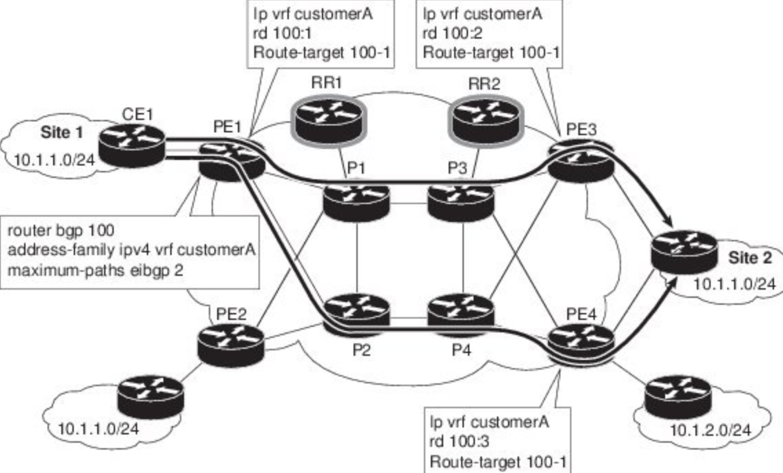 |
| Fig 1.1- Sample MPLS topology |
What is RD and why is the purpose of RD in MPLS network ?
Basics of VRF(Virtual Routing forwarding)
Today I am going to talk about one of the most important concept on which MPLS works. I understand many of you already knew about the MPLS but some of you guys are still want me to explain the concept of MPLS and the MPLS starts from the concept of VRF.
Before we will start with the concept of the VRF, Please subscribe our Youtube Channel, as we are going to upload many networking videos there soon.
Subscribe us on Youtube: http://y2u.be/0c4lMYVp9go
What is VRF- Virtual Routing forwarding ?
As you already knew that VRF stands for Virtual Routing Forwarding and is a separate routing table within a router. VRFs are to a router what VLANs are to a switch. Using VRFs, it is possible to virtualize a single router into several instances, each of them being (relatively) independent of each other, allowing for overlapping subnets, separate instances of routing protocols, separate set of interfaces assigned to each VRF.
In other words you can say that VRF stands for virtual routing and forwarding. When you create a vrf, you tell it what routes to import/export. Then you assign that vrf to an interface. Once the vrf is attached to Continue reading
Comparison between Cisco Catalyst 2950 Series Switches vs HP Pro-curve 2500/4000M
Today I am going to talk about the fair comparison between the two vendors access switches which are widely used in the various campus networks or you can use there in various enterprises. Both Switches are excellent with their features and in this article i will talk about the comparison with features.
Before we start with this article I would like to announce that we started our Youtube Channel and want your support to subscribe that channel. We are going to add many videos based on the networking basics, designs, configurations and pre-sales part. We are going to add the featured posts and the videos of the different vendors on the different technologies. You can subscribe us on the below mentioned link.
Before we start with this article I would like to announce that we started our Youtube Channel and want your support to subscribe that channel. We are going to add many videos based on the networking basics, designs, configurations and pre-sales part. We are going to add the featured posts and the videos of the different vendors on the different technologies. You can subscribe us on the below mentioned link.
Subscribe us on Youtube: http://y2u.be/0c4lMYVp9go
I Knew a huge support from your side operate us to make many more videos and articles for you. Thanks for supporting us in huge number. Now lets talk about the topic which i started from the beginning. Earlier i wrote an article regarding the comparison of Cisco 2960X vs Cisco 3650 vs Cisco 3850. The link for that article is shown as below.
Cloud Managed Wireless Solution : Cisco Meraki MR52
Today I am going to talk about the Cisco Meraki solution which is totally a cloud based managed system and the product name is Cisco Meraki MR52. It is based on the next generation wireless systems that can be deployed in various departments like Education systems, Manufacturing units, Offices, Enterprise networks and so on. The way Cisco Meraki works is totally a next generation revolution where all management can be done via cloud and you just need to deploy the hardware in your network to work.
What is the purpose to deploy and how much time it takes to configure Cisco Meraki MR52 ?
Well if you have the requirement to have the wireless network with various SSIDs you should go with the site surveys and on the basis of it you should go with the suitable model of the wireless WLCs. If I talk about the Cisco Meraki cloud managed MR52, It is simple to deploy and self configured via cloud. So you need not to require any resource for the configuration of the Meraki MR52 at the remote sites.
What is the throughput of the Cisco Meraki MR52 ?
Well Cisco Meraki MR52 is a high performance box and will provides Continue reading
Cloud Managed Wireless Systems : Cisco Meraki MR52
Today I am going to talk about the Cisco Meraki solution which is totally a cloud based managed system and the product name is Cisco Meraki MR52. It is based on the next generation wireless systems that can be deployed in various departments like Education systems, Manufacturing units, Offices, Enterprise networks and so on. The way Cisco Meraki works is totally a next generation revolution where all management can be done via cloud and you just need to deploy the hardware in your network to work.
What is the purpose to deploy and how much time it takes to configure Cisco Meraki MR52 ?
Well if you have the requirement to have the wireless network with various SSIDs you should go with the site surveys and on the basis of it you should go with the suitable model of the wireless WLCs. If I talk about the Cisco Meraki cloud managed MR52, It is simple to deploy and self configured via cloud. So you need not to require any resource for the configuration of the Meraki MR52 at the remote sites.
What is the throughput of the Cisco Meraki MR52 ?
Well Cisco Meraki Continue reading
What is the purpose to deploy and how much time it takes to configure Cisco Meraki MR52 ?
Well if you have the requirement to have the wireless network with various SSIDs you should go with the site surveys and on the basis of it you should go with the suitable model of the wireless WLCs. If I talk about the Cisco Meraki cloud managed MR52, It is simple to deploy and self configured via cloud. So you need not to require any resource for the configuration of the Meraki MR52 at the remote sites.
 |
| Fig 1.1- Cisco Meraki MR25 Wireless Systems |
What is the throughput of the Cisco Meraki MR52 ?
Well Cisco Meraki Continue reading
Introduction to Virtual Device Context- VDC in Nexus Environment
Today I am going to talk about the virtual feature in the Cisco Nexus devices called as VDC. VDC stands for Virtual Device Context. With the help of VDC we can convert a single physical Nexus device or chassis into various virtual devices or chassis and that depends upon the SUP engine we are using in the device.
Keep in mind that VDC feature is not available in any of the Nexus device below 7K. So now we have the question like how many VDCs we can create in a single Nexus Chassis.
Look at the below picture, you are going to replace Core and Distribution physical switches with the a single Nexus Switch where we create two different VDC for Core and Aggregation layer. The picture defines the right way for your 3 layer architecture in the Datacenter environment.
Hope picture and the below mentioned description will help you guys to understand the concept of the VDC in the datacenter environment.
How many VDC, we can create ?
Well VDC depends upon the SUP engine we are using. Like if we are using SUP 1, we can create maximum of 3 VDCs, if we are using Continue reading
Keep in mind that VDC feature is not available in any of the Nexus device below 7K. So now we have the question like how many VDCs we can create in a single Nexus Chassis.
Look at the below picture, you are going to replace Core and Distribution physical switches with the a single Nexus Switch where we create two different VDC for Core and Aggregation layer. The picture defines the right way for your 3 layer architecture in the Datacenter environment.
Hope picture and the below mentioned description will help you guys to understand the concept of the VDC in the datacenter environment.
 |
| Fig 1.1- VDC Topology |
How many VDC, we can create ?
Well VDC depends upon the SUP engine we are using. Like if we are using SUP 1, we can create maximum of 3 VDCs, if we are using Continue reading
Basic Router Configurations on Cisco Router
Today I am going to talk about the basic configurations on Cisco routers where i can define the basic commands like setting console password, assign VTY password, configuring IP addresses on the interfaces, Configuring the router for SSH access, Configuring basic IPv6 configurations on the router, configuring trunk based inter-VLAN routing, configuring IPv6 configurations manually and at last configuring OSPFv6 with the use of IPv6.
This is a basic article for the starters who are going to configure the router from the scratch. Most of the basic configurations are for demo purposes and you can use your IP addresses as per requirements in your network. Lets start with the basic configurations on the router now.
Above is the basic network topology where we have 3 layer architecture with the Cisco ASA firewalls and the routers. We are going to configure WAN routers with the basic configurations
This is a basic article for the starters who are going to configure the router from the scratch. Most of the basic configurations are for demo purposes and you can use your IP addresses as per requirements in your network. Lets start with the basic configurations on the router now.
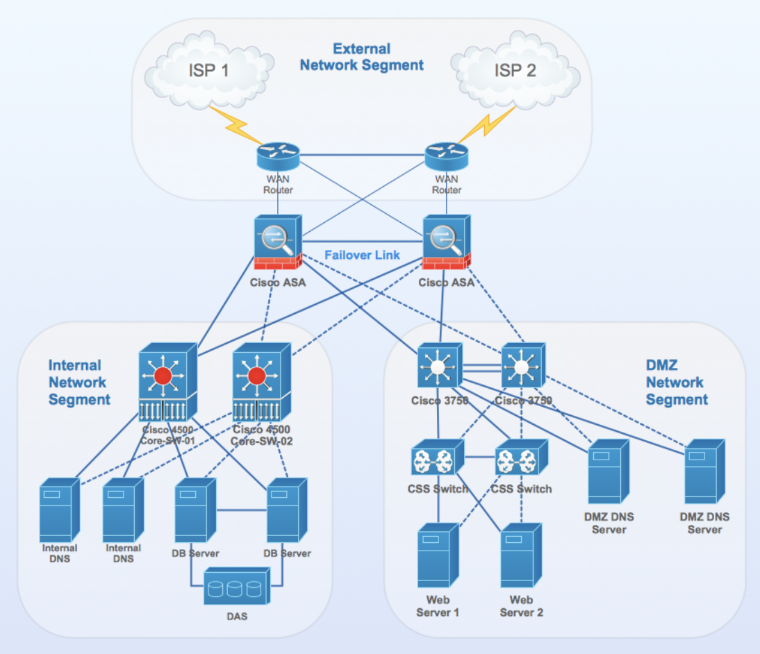 |
| Fig 1.1- Basic Network Topology |
Configure the Basic router
Router> enable
Router# config terminal
Router# config terminal
Router(config)# hostname ttlbits_ttlbits_R1
ttlbits_R1(config)# no ip domain-lookup
ttlbits_R1(config)# security passwords min-length 10
ttlbits_R1(config)# enable secret cisco12345
Now let's configure the console password on the Cisco routers, below is the basic example showing the configurations of console on router.
Setting Continue reading
Configuring vPC on Cisco Nexus Devices
Today I am going to talk about the configurations of vPC on Cisco Nexus devices as i already talked about vPC in my earlier articles. If you want to have a look on the vPC basics check the below mentioned link for your references.
A short Story on vPC- Virtual Port Channel in Cisco Datacenter Environment
There are lot of questions how and why we are using the vPC in the Datacenter environment while some asked me about the difference in the vPC and VSS. Please have a look on the below link for the comparison of vPC and VSS.
Features comparison : Cisco vPC and Cisco VSS
Apart from the above mentioned articles, I wrote on the different technologies used by other vendors same as Cisco uses vPC and VSS. Below is the link defining the same
Feature Comparison: Juniper VCF vs HP IRF vs Cisco VSS vs Cisco vPC
From all the above articles, I think now you got the basics on vPC and VSS, but in this article I will talk about the vPC configuration in details with the diagram. The topology used in the article will be sample topology and has no relevance with any of Continue reading
Introduction to Network Time Protocol (NTP) and Basic Configurations
Today I am going to discuss about the NTP or so called Network Time Protocol. I knew many of you already aware about the use of NTP in our networks but as it was asked by some guys who follow our blogs, So I am happy to explain the NTP little bit with the configurations.
What is Network Time Protocol or NTP ?
So, NTP is Network Time Protocol which is generally used to synchronise of the devices to some specific time references. NTP uses UDP protocol to communicate with all the devices in the network and all NTP communications in the network will be synchronised with the defined universal time in the network.
How they synchronise with the time source ?
NTP server usually receives its time from a trustworthy time source, such as a radio clock attached to a time server, and then distributes this time across the network. NTP is extremely efficient and there is no more than one packet per minute is necessary to synchronize two machines to within a millisecond of each other
An Network Time Protocol actually uses a layer to describe the distance between a network device and an authoritative time source
- A layer 1 time server Continue reading
Introduction to TACACS and TACACS+ (Terminal Access Controller Access Control System)
Today I am going to talk about the TACACS and TACACS+ basics with you. I am sure most of you already knew TACACS and TACACS+ as many of you worked and configured the configuration on your devices whether it will Cisco, Juniper or any other vendor in your network.
Here in this article I am Just talk about TACACS and TACACS+ as follow.
What is TACACS and TACACS+ ?
TACACS and TACACS+
Here in this article I am Just talk about TACACS and TACACS+ as follow.
What is TACACS and TACACS+ ?
Well all of you already listern this term so many times but many of you confuse what is TACACS and TACACS+.
Terminal Access Controller Access Control System or called as TACACS is a authentication protocol and is commonly used within the UNIX based networks that allows a remote access server to forward a user's logon password to an authentication server to determine whether access can be allowed to a given system.
TACACS and TACACS+
TACACS is a simple UDP-based access control protocol originally developed by BBN for MILNET. TACACS+ is an enhancement to TACACS and uses TCP to ensure reliable delivery.
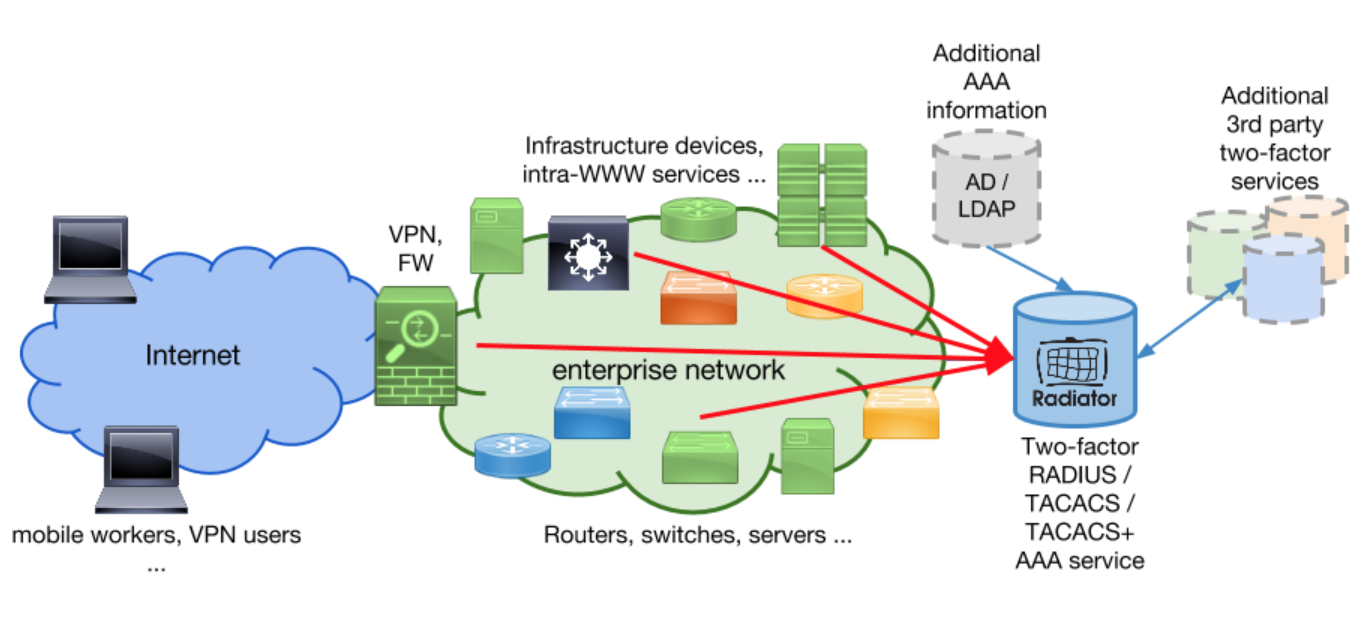 |
| Fig 1.1- TACACS and TACACS+ Server |
TACACS+ is an enhancement to the TACACS security protocol. TACACS+ improves on TACACS by separating the functions of authentication, authorization, and accounting (AAA) and Continue reading
Difference Between Cisco ACI Multi-Pod Vs Cisco ACI Multi-Site
Today I am going to talk about the difference between the Cisco ACI Multi-Site and Cisco ACI Multi-Pod deployment. I already talk about the basics of Cisco ACI Multi-Site and Cisco ACI Multi-Pod in my earlier posts. If you want to look through it, Please have a look to the below link to understand the Cisco ACI Multi-Pod and Cisco ACI Multi-Site
Introduction to Cisco ACI stretched fabric and ACI Multi-pod Fabric Designs
Introduction to ACI Multi-Site Fabric Design Network
Hope you go through the above links to understand, So let me talk about the basic difference between the Cisco ACI Multi-Pod and Cisco ACI Multi-Site.
Below are the difference as :
Introduction to Cisco ACI stretched fabric and ACI Multi-pod Fabric Designs
Introduction to ACI Multi-Site Fabric Design Network
Hope you go through the above links to understand, So let me talk about the basic difference between the Cisco ACI Multi-Pod and Cisco ACI Multi-Site.
 |
| Fig 1.1- ACI Multi-Site and Multi-Pod Deployments |
Below are the difference as :
- In Multi-Pod you can have, Full ACI functionality across an entire Multi-Pod fabric while in in Multi-Site you can have Tenants, Applications, VRFs, BDs, Subnets, EPGs (including μSeg), policies stretched across ACI fabrics
- Availability Zone: In Multi-Pod, Single availability zone with one APIC cluster for an entire Multi-Pod fabric that provides central point of management while in Multi-Site we have Multiple availability zones.In each fabric with its separate APIC cluster is an availability zone managed by Multi-Site.
- VM Migration : In Multi-Pod, Live Continue reading
Introduction to RADIUS- Remote Authentication Dial-In User Service
Today I am going to talk about the major component of the network which provide you the authentication services whenever called from the user. The major component is called as RADIUS. This major component hosted on the server which is capable of giving the right reports of the users authentication. Let's talk about the RADIUS server or so called Remote Authentication Dial-In User Service
What is RADIUS- Remote Authentication Dial-In User Service?
What is RADIUS- Remote Authentication Dial-In User Service?
RADIUS( Remote Authentication Dial-In User Service) is a server systems with which we can secures our networks against unauthorised access. So RADIUS clients run on supported routers and switches. Clients send authentication requests to a central RADIUS server, which contains all user authentication and network service access information.
If i talk about RADIUS in other simpler words you can say that the system is a network protocol by which we are defining rules and conventions for communication between network devices - for remote user authentication and accounting.
What is the main purpose of RADIUS servers ?
Well the major purpose of the RADIUS server in the network is described as below.
- Authenticates users or devices before allowing them access to a network
- Authorises those users or devices Continue reading
Introduction to Point to Point Authentication : PAP and CHAP protocols
Today I am going to talk about the PAP- Password Authentication Protocol and CHAP- challenge handshake authentication protocol. So let's talk about PAP and CHAP one by one.
PAP and CHAP is one of the basic and most important topic for CCNA candidates or the freshers who are going to work on the Point to point networks.
Before we are starting with the PAP and CHAP protocols, I would like to tell you that PAP and CHAP is the authentication procedure in Point to point network. So if you are using Point to point networks in your architecture you should opt for PAP or CHAP protocols as per the design required.
Below is the example showing the pictorial representation where we are defining the acceptance and the refusal of the connection in both the cases.
PAP- Password Authentication Protocol
So PAP is a password-based authentication protocol used by Point to Point Protocol (PPP) to validate users. PAP generally consider as a very basic two-way process. There is no encryption. The username and password are sent in plain text. If it is accepted, the connection is allowed.
The authentication phase of a PPP session is optional. If used, you can authenticate the Continue reading
Introduction to ACI Multi-Site Fabric Design Network
In my earlier post I talk about the ACI stretched Fabric and ACI multi-pod fabric designs with single and multiple APIC clusters. Now I am going to talk about the basics of the Cisco ACI Multi-site fabric design network in my article. If you want to have a look for my earlier article, please go through the below mentioned link and review before we will start with the Cisco ACI multi-site fabric network design.
Introduction to Cisco ACI stretched fabric and ACI Multi-pod Fabric Designs
So in short, you now understand the Cisco single-pod, Cisco ACI stretched fabric and Cisco ACI multi-pod fabric design. Now we are going to talk about the next level of Cisco ACI deployment model and this model is called as Cisco ACI Multi-site fabric design.
Cisco ACI Multi-site Fabric Network Design
Making more innovation in the Cisco ACI with the APIC 2.0 release, Cisco said that a Multi-Site design is the architecture interconnecting multiple APIC cluster domains with their associated pods.
A Multi-Site design could also be called a Multi-Fabric design, because it interconnects separate availability zones (fabrics), each deployed either as a single pod or multiple pods (a Multi-Pod design). Below is Continue reading
Introduction to Cisco ACI stretched fabric and ACI Multi-pod Fabric Designs
Today I am going to talk about Cisco ACI where Cisco is providing two different solutions on Cisco ACI. One solution is Cisco ACI Multi-pod and other solution is named as Cisco ACI Multi-Site design or architecture.
Earlier Cisco ACI multi-pod environment we were doing the ACI stretched Fabric design but then Cisco come up with the solution called as Cisco ACI multi-pod.
What is Cisco ACI Multi-pod ?
Well ACI multi-pod is a kind of ACI stretched Fabric design with more benefits and features. In simple words we can say that ACI multi-pod is a multiple ACI fabrics that is under control of single management or administration.
What is the key difference of ACI stretched fabric design and ACI multi-pod ?
Let's talk about the ACI stretched fabric design, Let us suppose we have two ACI fabric design where we have Spine-Leaf architecture. One is ACI-I and other is ACI-II, if you are going to connect the leaf switches of ACI-I with the spine switches of ACI-II and leaf switches of ACI-II with spine switches of ACI-I makes ACI Stretched fabric design. Below diagram shows the best way of Cisco ACI stretched fabric design between three ACI fabric networks.
 |
| Continue reading |