Author Archives: ddib
Author Archives: ddib
It’s been a while since I did an on-premises installation of the Catalyst SDWAN controllers and as I recently had to go through the process, I thought I would document it and post it here for people that want to build their own lab.
The first thing that happens after booting the Manager is that you need to login with admin/admin and then set a new password:
vmanage login: Admin
Password:
Welcome to Viptela CLI
admin connected from 127.0.0.1 using console on vmanage
You must set an initial admin password different from default password.
Password:
Re-enter password:
After that we must select the persona (what services the Manager should run). For a non-cluster install it’s going to be both COMPUTE and DATA:
1) COMPUTE_AND_DATA
2) DATA
3) COMPUTE
Select persona for vManage [1, 2 or 3]:
Select 1.
You will be asked to confirm:
You chose persona COMPUTE_AND_DATA (1)
Are you sure? [y/n]
Type y.
You will then be asked what storage device to be used (you need a secondary disk):
vManage has been deployed with persona : {"persona": "COMPUTE_AND_DATA"}
Available storage devices:
sdb      100GB
1) sdb
Select storage device to use:
Here I’ll select 1.
Step CA is an open-source private CA made by Smallstep. I will use it to generate certificates for some componenents in my lab.
First we install the dependencies:
sudo apt-get update && sudo apt-get install -y --no-install-recommends curl gpg ca-certificates
Then we get the Smallstep repository signing key:
sudo curl -fsSL https://packages.smallstep.com/keys/apt/repo-signing-key.gpg -o /etc/apt/keyrings/smallstep.asc
Then we add the Smallstep repository:
cat << 'EOF' | sudo tee /etc/apt/sources.list.d/smallstep.sources > /dev/null
Types: deb
URIs: https://packages.smallstep.com/stable/debian
Suites: debs
Components: main
Signed-By: /etc/apt/keyrings/smallstep.asc
EOF
Then we install step-cli and step-ca:
sudo apt-get update && sudo apt-get -y install step-cli step-ca
Then we check the install:
step-ca version
step version
Smallstep CA/0.30.2 (linux/amd64)
Release Date: 2026-03-23T00:18:00Z
Smallstep CLI/0.30.4 (linux/amd64)
Release Date: 2026-06-10T06:10:28Z
Next, we’ll run the initializer:
step ca init \ --name "lostintransit.se" \ --dns "stepca.lostintransit.se" \ --address ":443" \ --provisioner "[email protected]"Deployment Type: Standalone Choose a password for your CA keys and first provisioner.
Dnsmasq is an application which has features like DNS caching, DHCP server, and so on. It’s useful as a DNS server in a homelab as it can reply to DNS queries for what’s in its database, and forward everything else to an authoritative server or recursive resolver. This is useful in my lab as I want to resolve for example gitlab.lostintransit.se locally, but lostintransit.se (my web server) or any other domains via recursive resolvers. Most DNS servers are authoritative for a zone or parts of a zone, but dnsmasq responds only to what it knows and forwards everything else, which is perfect for my needs.
First I’ll configure a static IP on the host by modifying the file in /etc/netplan:
sudo vi 50-cloud-init.yaml
The contents are now:
sudo cat 50-cloud-init.yaml
network:
  version: 2
  ethernets:
    ens160:
      dhcp4: no
      addresses:
        - 192.168.128.53/24
      routes:
        - to: default
          via: 192.168.128.1
      nameservers:
        addresses:
          - 8.8.8.8
          - 8.8.4.4
I’m using recursive resolvers for now but will update it later.
Then apply the configuration:
sudo netplan apply
The IP has been updated:
ip addr show ens160
2: ens160: <BROADCAST,MULTICAST,UP,LOWER_UP>  Continue reading
I’m reorganizing some things in my homelab and wanted to check how many hosts are alive in a /24. The simple check, while not perfect, is to ping all the hosts and see who responds. I used Claude to generate some Python for me and noticed it used some tools I had not used before, to run code concurrently, which really speeds up things like scanning a /24 for alive hosts. In this post I’ll compare running sequentially vs concurrently and break down the code.
Running something sequentially means that every job, such as checking if an IP is alive, must run to completion before the next job starts. This is highly inefficient, of course, mainly for two reasons:
Especially when the job involves something like ping, we must give hosts a reasonable time to respond, so we’ll wait up to a second. We also can’t one-shot the ping because what if we have no ARP entry for the host we are pinging (assuming same subnet)? Then, a host that is alive could be reported as dead due to the missing ARP entry.
I’ll Continue reading
I need an on-premises Git server for my labbing so this post will describe how to install GitLab Community Edition (CE). My install is on Ubuntu 24.04 LTS, specifically ubuntu-24.04.4-live-server-amd64, but you can use whatever works for you.
First I upgrade all the packages:
sudo apt update && sudo apt upgrade -y
Then install the dependencies for GitLab CE:
sudo apt install ca-certificates curl openssh-server postfix tzdata perl
In the installation for postfix, select Internet Site and then enter the server’s domain name. This is really only if you need to send e-mails.
Then reboot:
sudo reboot
I configure the hostname of the server:
sudo hostnamectl set-hostname gitlab.lab.local
I’ll update this later when installing a certificate for the server.
Then download the script that will add GitLab’s package repository to the system’s apt sources:
curl https://packages.gitlab.com/install/repositories/gitlab/gitlab-ce/script.deb.sh | sudo bash
Next we setup the EXTERNAL_URL environment variable and install version 18.4 (I needed this specific version):
sudo EXTERNAL_URL="http://gitlab.lab.local" apt install -y gitlab-ce=18.4.*
The EXTERNAL_URL variable is read by the GitLab installer and this is the URL that the server will be available via. I’ll update Continue reading
Cisco just announced major updates to their certification portfolio. Here’s what’s changing:
Effective February 2027, the CCNA is getting a major update. The future networking administrator/engineer will be more of an orchestrator than operator. Meaning that punching commands on the CLI will only be a small part of the future job role. Instead, you must be able to design, secure, and optimize increasingly autonomous networks. To be job-ready, you’ll need to learn how to:
The CCNA is about to get a whole lot more practical! Here’s what’s changing:
Troubleshooting gets a front seat. Employers value troubleshooting over reciting commands. Every domain will diagnostics and problem resolution. Think of the old TSHOOT CCNP exam, but instead of a separate exam, this is the format of the CCNA now. I’m really excited about this!
Security everywhere. We can no longer afford to think of security only as a separate domain, it needs to be part of everything we do. The new exam Continue reading
Yesterday I took and passed the Cisco AUTOCOR (previously DEVCOR) exam which is the core exam for CCNP Automation. That means I need a specialist exam to become CCNP Automation certified. It also means I’m qualified to sit the CCIE Automation lab.
What did I think of the exam?
As with any exam, there is good and bad. I’ll start with the good.
The exam aligned well with the blueprint. I didn’t feel there were any real surprises or questions on items that weren’t part of the blueprint.
There wasn’t a lot of trivia. No memorization of specific API endpoints or anything like that.
The exam experience was fine. I took it in a testing facility, which I prefer, and I had no issues. I was provided with earplugs which was nice to stay focused although this is a small facility and there was only one other candidate.
I liked the different types of questions. You have your standard multiple choice, single answer and multiple choice, multiple answer, but also fill in the blanks, and lablets. It’s nice that there is quite a bit of code in the exam, it is an automation exam after all. I also think it’s Continue reading
A long long time ago, BGP implementations would use a Maximum Segment Size (MSS) of 536 bytes for BGP peerings. Why 536? Because in RFC 791, the original IP RFC, the maximum length of a datagram is defined as follows:
Total Length:  16 bits

    Total Length is the length of the datagram, measured in octets,
    including internet header and data.  This field allows the length of
    a datagram to be up to 65,535 octets.  Such long datagrams are
    impractical for most hosts and networks.  All hosts must be prepared
    to accept datagrams of up to 576 octets (whether they arrive whole
    or in fragments).  It is recommended that hosts only send datagrams
    larger than 576 octets if they have assurance that the destination
    is prepared to accept the larger datagrams.

    The number 576 is selected to allow a reasonable sized data block to
    be transmitted in addition to the required header information.  For
    example, this size allows a data block of 512 octets plus 64 header
    octets to fit in a datagram.  The maximal internet header is 60
    octets, and a typical internet header is 20 octets, allowing a
    margin for headers of higher level protocols.
The idea was to Continue reading
Link state protocols like OSPF and IS-IS use the Shortest Path First (SPF) algorithm developed by Edsger Dijkstra. Edsger was a Dutch computer scientist, programmer, software engineer, mathematician, and science essayist. He wanted to solve the problem of finding the shortest distance between two cities such as Rotterdam and Groningen. The solution came to him when sitting in a café and the rest is history. SPF is used in many applications, such as GPS, but also in routing protocols, which I’ll cover today.
To explain SPF, I’ll be working with the following topology:
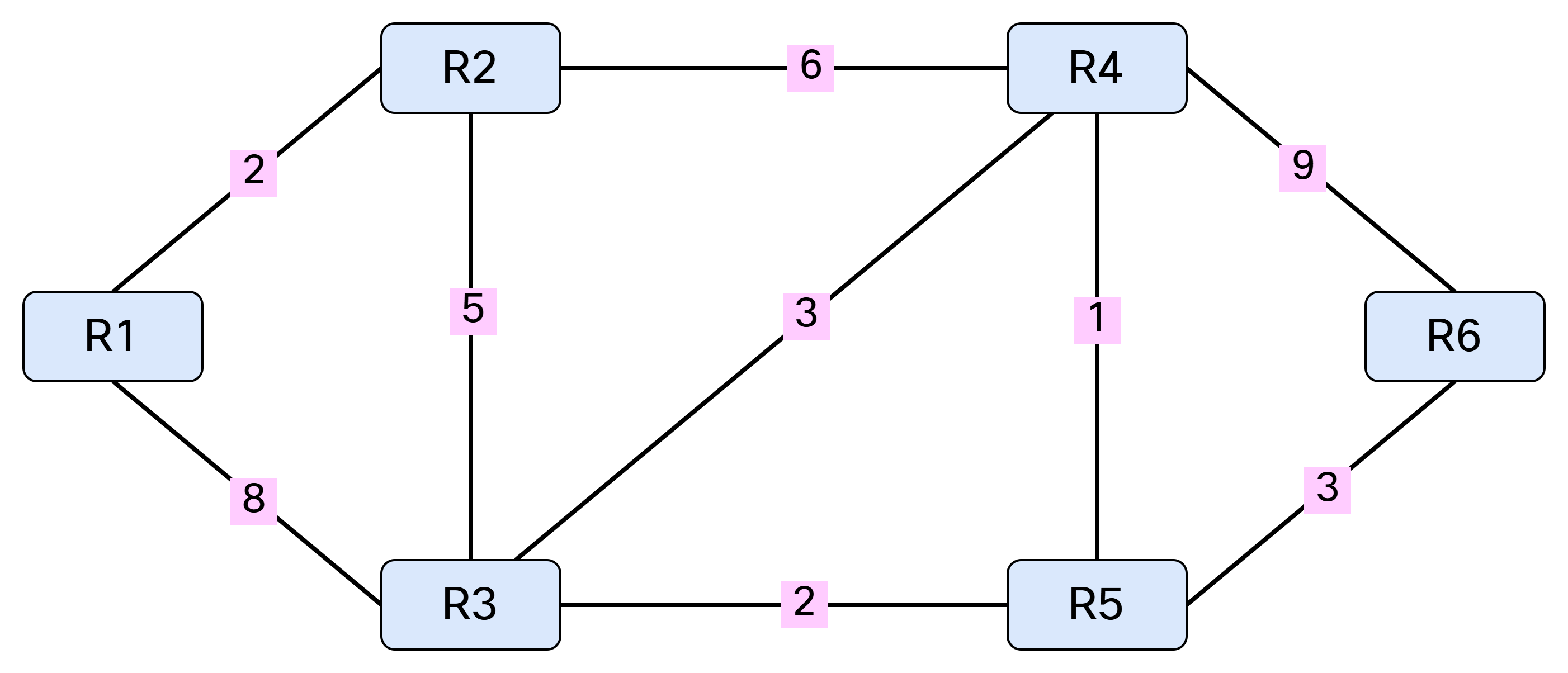
Note that SPF only works with a weighted graph where we have positive weights. I’m using symmetrical costs, although you could have different costs in each direction. Before running SPF, we need to build our Link State Database (LSDB) and I’ll be using IS-IS in my lab for this purpose. Based on the topology above, we can build a table showing the cost between the nodes:
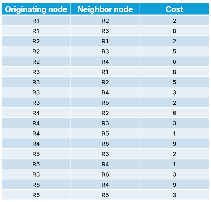
This triplet of information consists of originating node, neighbor node, and cost. It can also be represented as [R1, R2, 2], [R1, R3, 8], [R2, R1, 2], [R2, R3, 5], [R2, R4, 6], [R3, R1, 8], [R3, R2, 5], [R3, R4, Continue reading
In many ways, IS-IS is a simpler, and perhaps more elegant, routing protocol than OSPF. However, it often gets misunderstood. Perhaps due to its roots in OSI or perhaps because it’s not as widely deployed as OSPF. Some of the confusion come from how it behaves on multi-access networks. What is a Designated Intermediate System (DIS)? Why do we need a pseudonode? How do we flood Link State PDUs (LSPs)? In this post, I’ll cover all of that and more. This is going to be a deep dive so save this blog for when you have some time to focus.
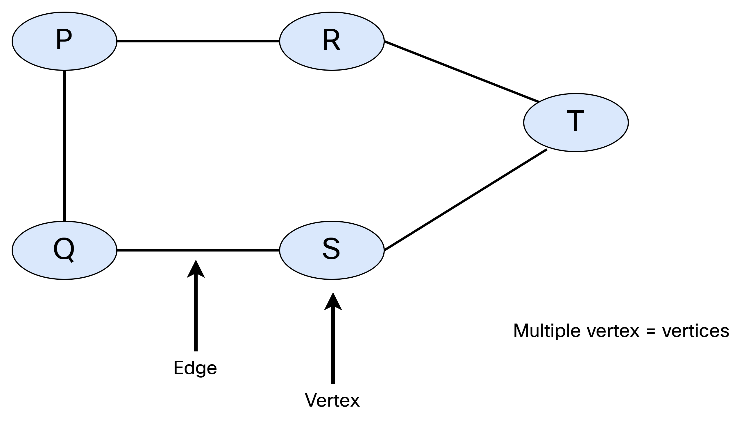
IS-IS is a link state protocol, which means that we need to build a link state database that describes how all the intermediate systems (routers) are interconnected, and what prefixes they are associated with. Simply put, we need to build a graph. Let’s do a quick recap of graph theory.
A graph consists of vertices (nodes) and edges (links). When referring to a single node, it’s called a vertex. This is shown below:
There are different types of graphs. They can be undirected and unweighted:
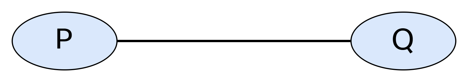
With this type of graph, there is no weight assigned and there is no way Continue reading
In this post we’ll add a Network Authentication Device (NAD) to ISE to perform TACACS+ authentication and authorization. We’ll also do a deep dive on AAA commands on the NAD. First let’s start with the overall goal of the lab and an overview of how TACACS+ works.
The goal of the lab is to have two users, Bob and Alice, where Bob works in the NOC and Alice is a network admin. Based on the AD group they belong to, they should get different permissions when administrating devices. Alice will be able to use all commands, while Bob will only be able to use basic commands. This is shown below:
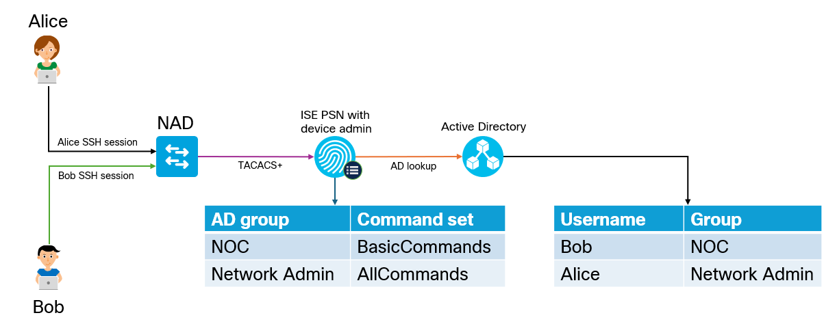
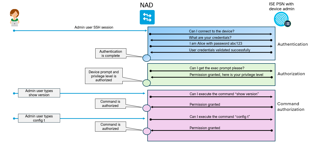
Why would we use TACACS+ over RADIUS? The main reason is that it gives us per command authorization and accounting. The overall flow of TACACS+ is shown below:
To get things started, we must first enable TACACS+ on the PSN. Go to Administration -> Deployment located under System:
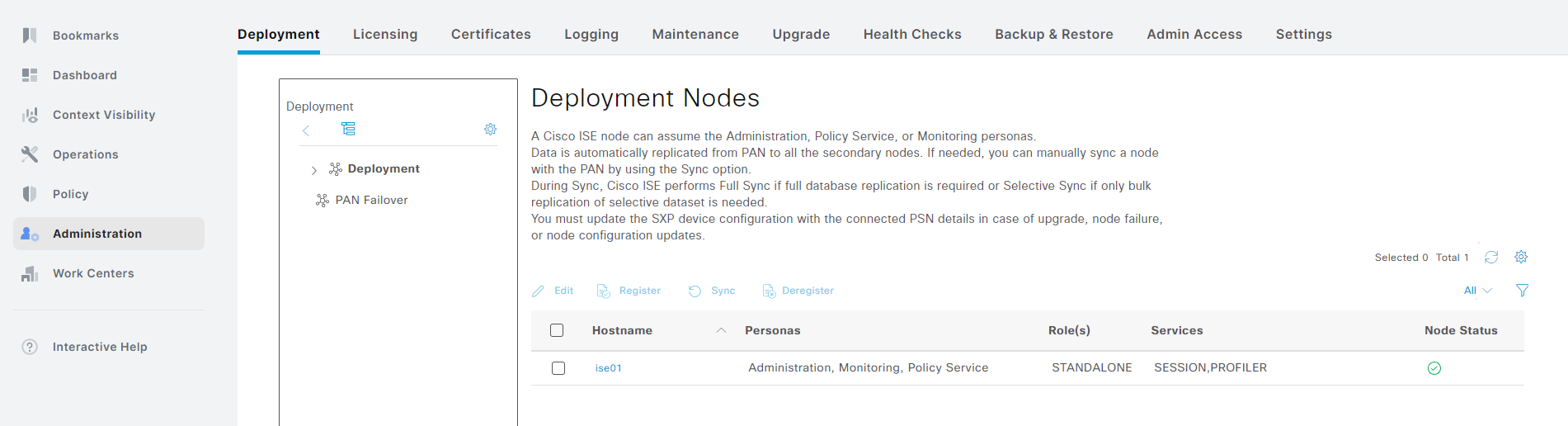
Click the > symbol next to Deployment and select your PSN that you want to enable TACACS+ on:
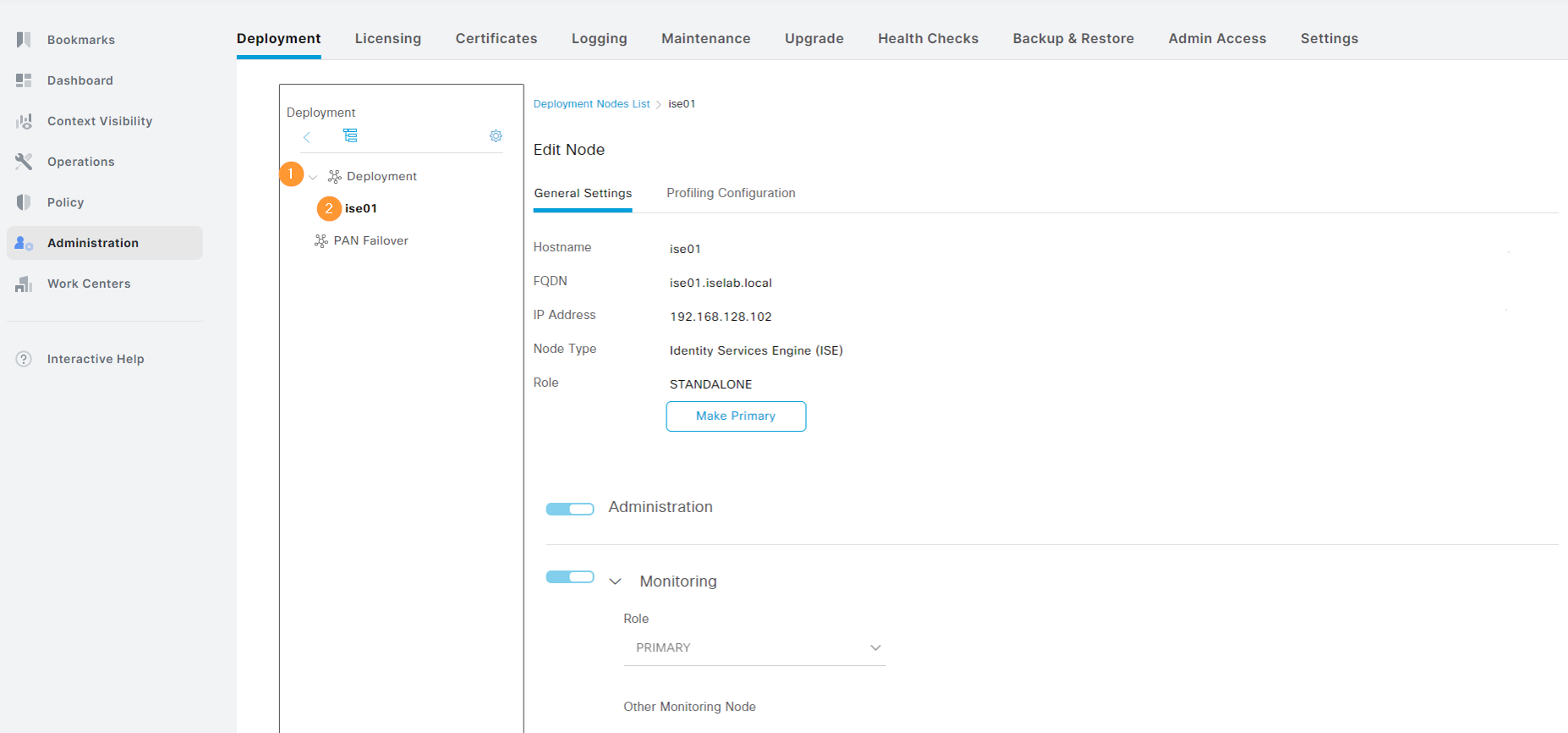
Scroll down to the Policy Service part. Notice that Device Admin is currently not enabled:
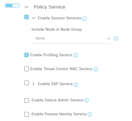
Select Enable Device Admin Service. You Continue reading
The ISE evaluation license gives you 90 days of full access and after that you won’t be able to make any changes. Currently, my server has 28 days remaining:

As I intend to keep labbing, I’m going to perform a backup and restore where I’ll restore the configuration on another VM that I’ll be installing. Note that this can be automated, but in this post we’re going to focus on the process of doing it manually to understand what steps are involved.
The steps that will be performed are:
The configuration backup will give us everything we need to restore all the system settings and policies. The operational backup gives us data such as logs. While the configuration backup includes the trusted- and system certificates, it’s good to also export them separately in case you need to perform a restore using another method.
The first thing I’m going to do is to install SFTP on my Windows server using Continue reading
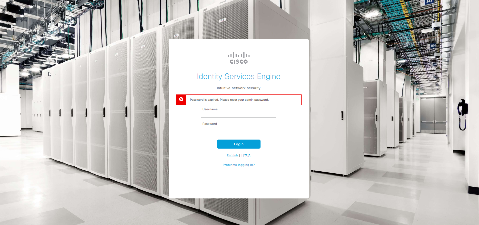
This is a quick post to describe the default behavior of the admin user GUI access in ISE, which gets locked after 45 days, if you haven’t changed the password. You’ll get something like this in the GUI:
While GUI access is prevented, you can still login via SSH and that’s how you’re going to recover the account. SSH to ISE using the admin account. Then issue the following command:
ise01/admin#application reset-passwd ise admin
Enter new password:
Confirm new password:

Password reset successfully.
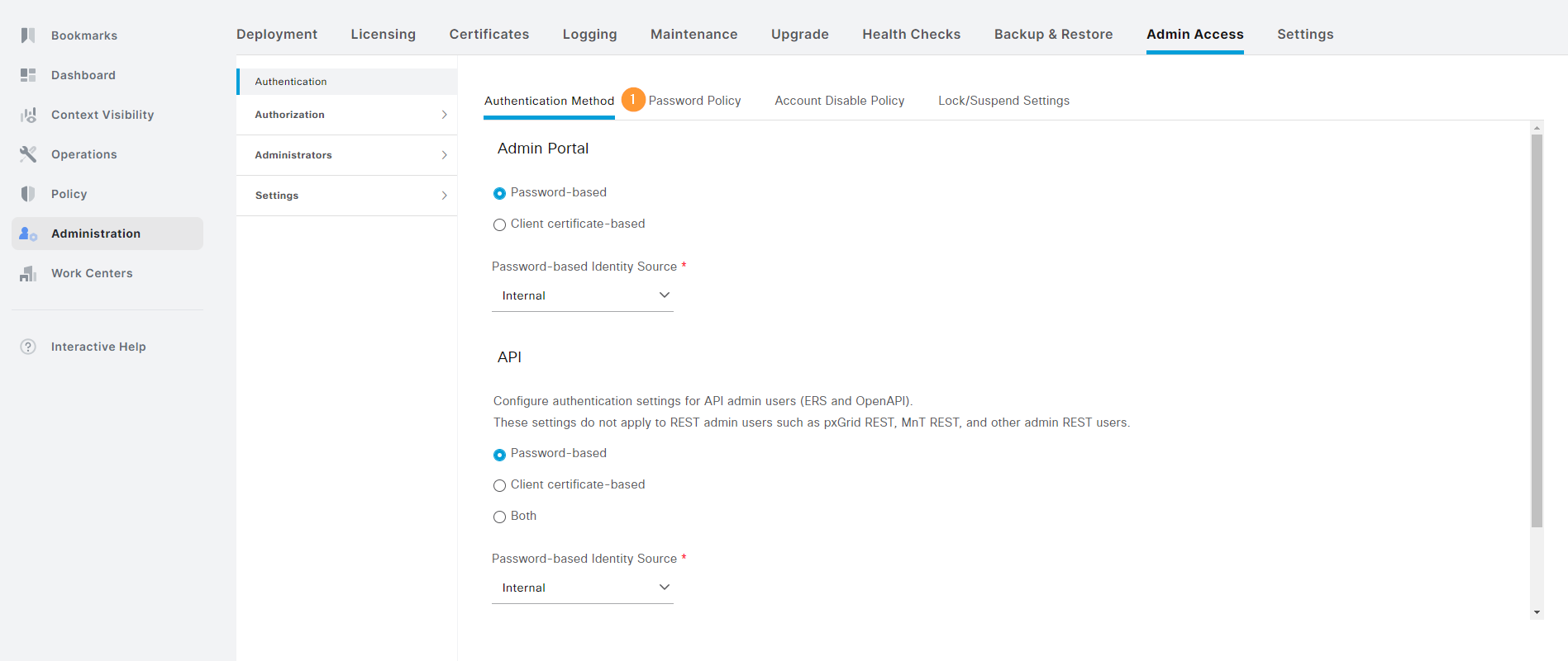
If you want to change the password policy, go to Administration -> Admin Access under System and click Password Policy:
Notice the checkbox that says that the account expires after 45 days:
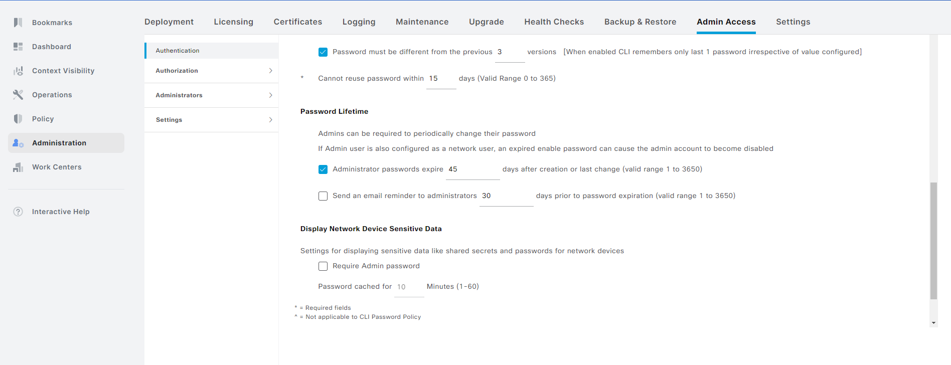
Uncheck this box if you don’t want to have the account expire:
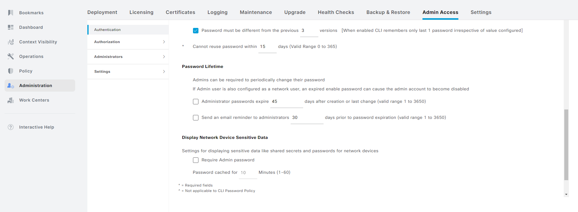
Don’t forget to click Save. That’s it! That’s how you recover the account and prevent it from happening again. Note that this is for a private lab. You should adhere to any policies you have on password rotation in your organization.
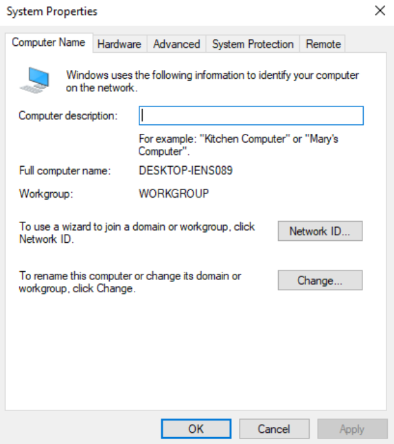
In this post we’ll domain join a Windows 10 VM to test the GPOs that were created in a previous post. First, let’s verify that the computer is not joined to a domain:
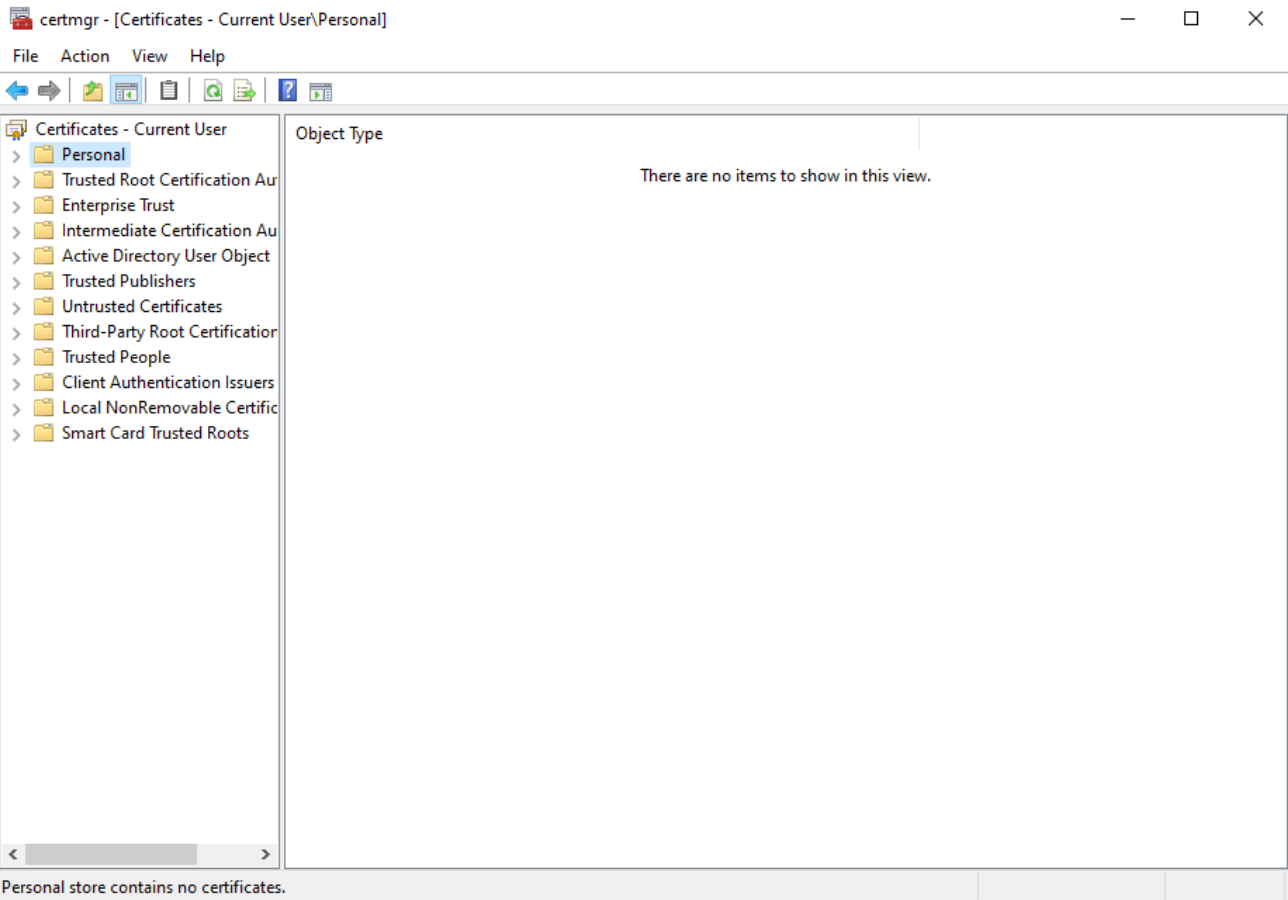
There is currently no user certificate:
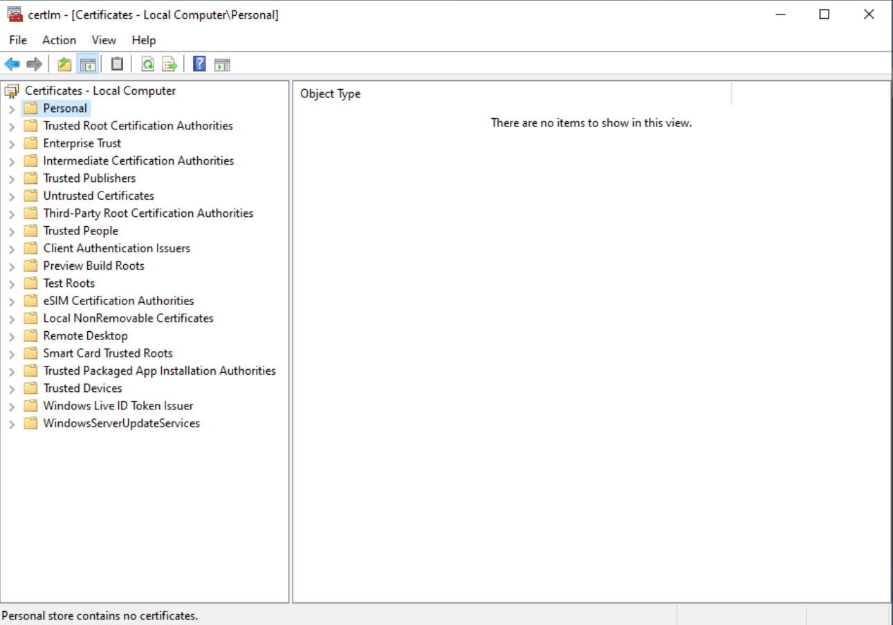
There is also no computer certificate:
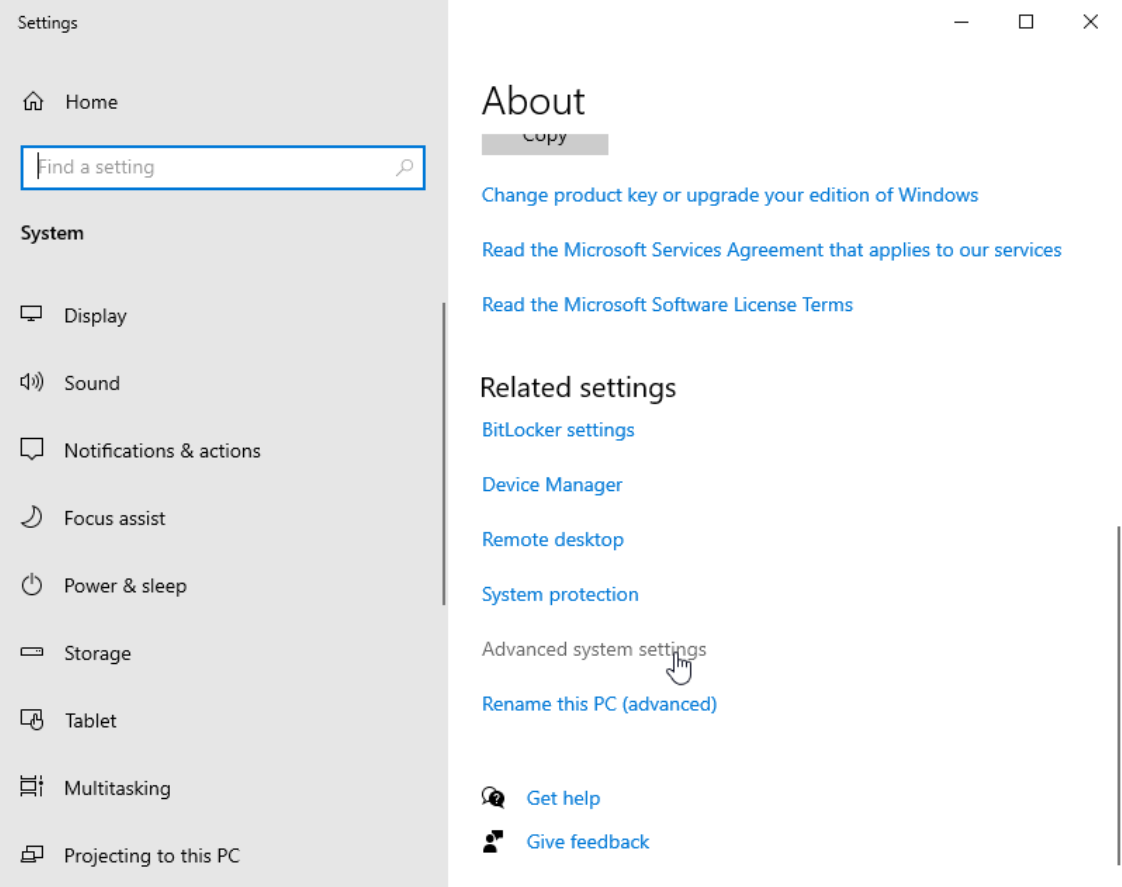
To domain join the computer, we’ll go to Control Panel -> System and Security -> System and the click Advanced system settings:
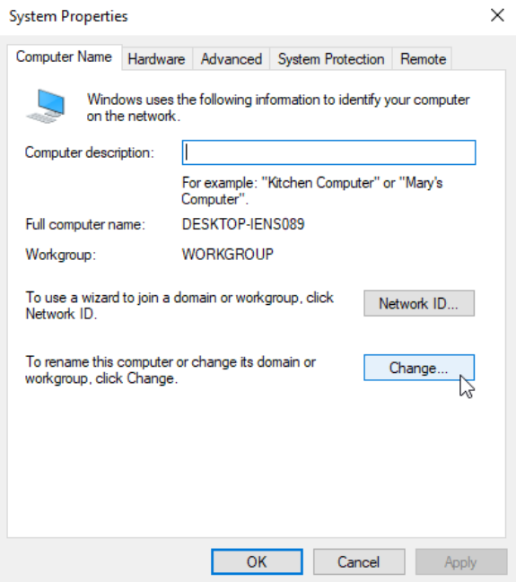
Go to Computer Name and click Change…:
Select Member of Domain and enter the domain name (iselab.local in my lab):
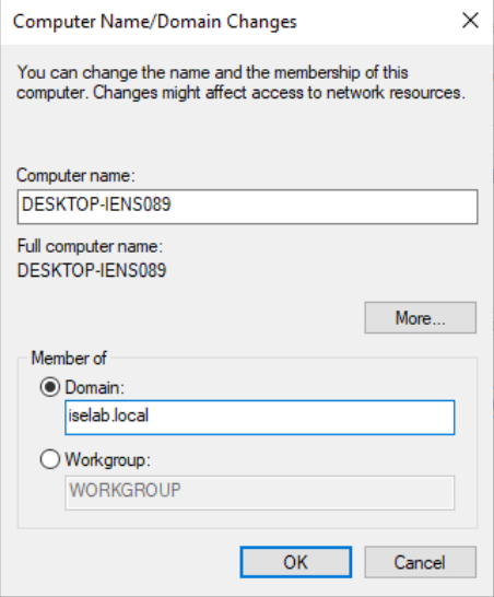
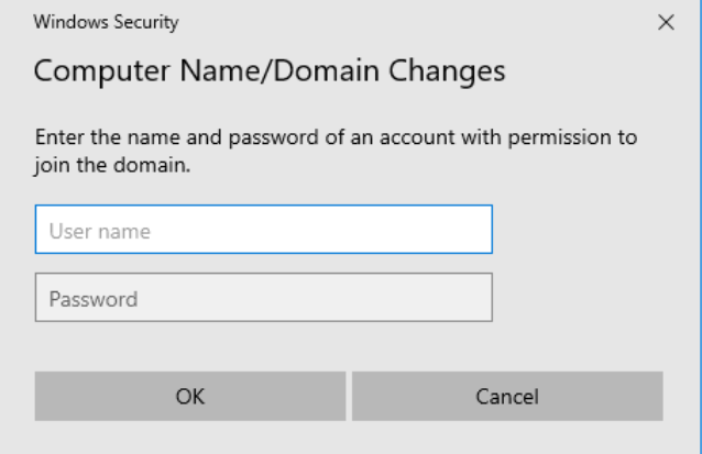
Click OK. You’ll then be prompted for credentials with permission to join the domain:
The computer has been joined to the domain:
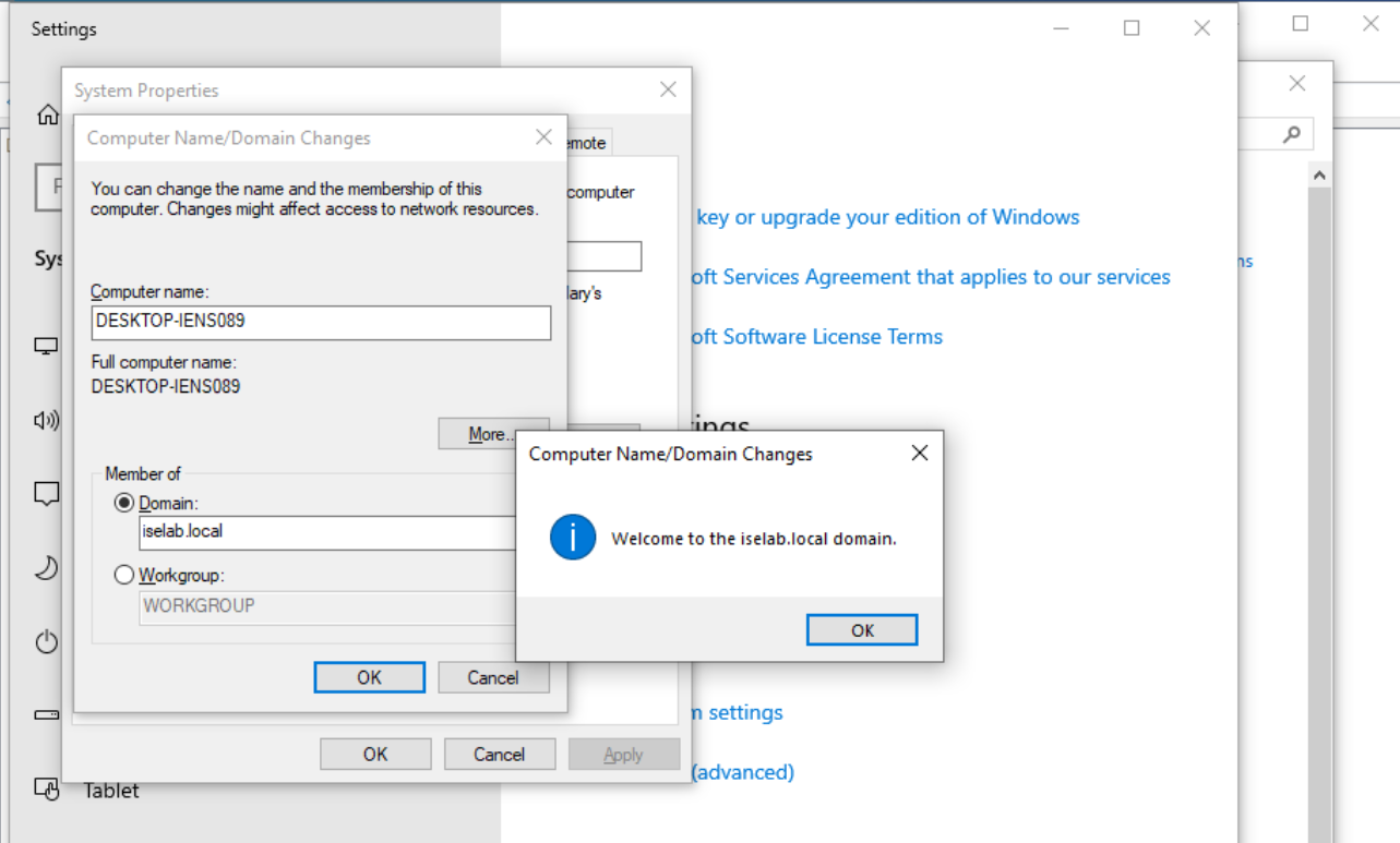
The computer will have to be restarted as part of joining the domain:
Select Restart Now to restart:
It will take some time…:

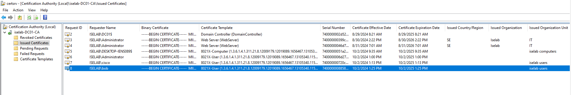
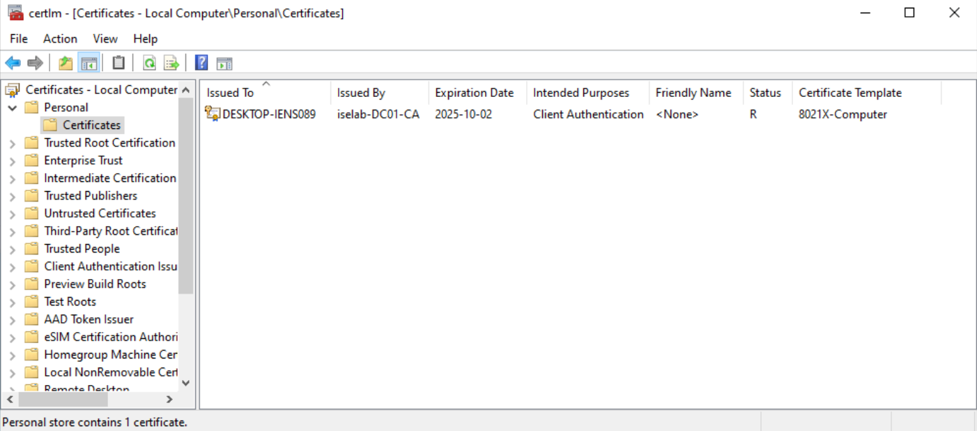
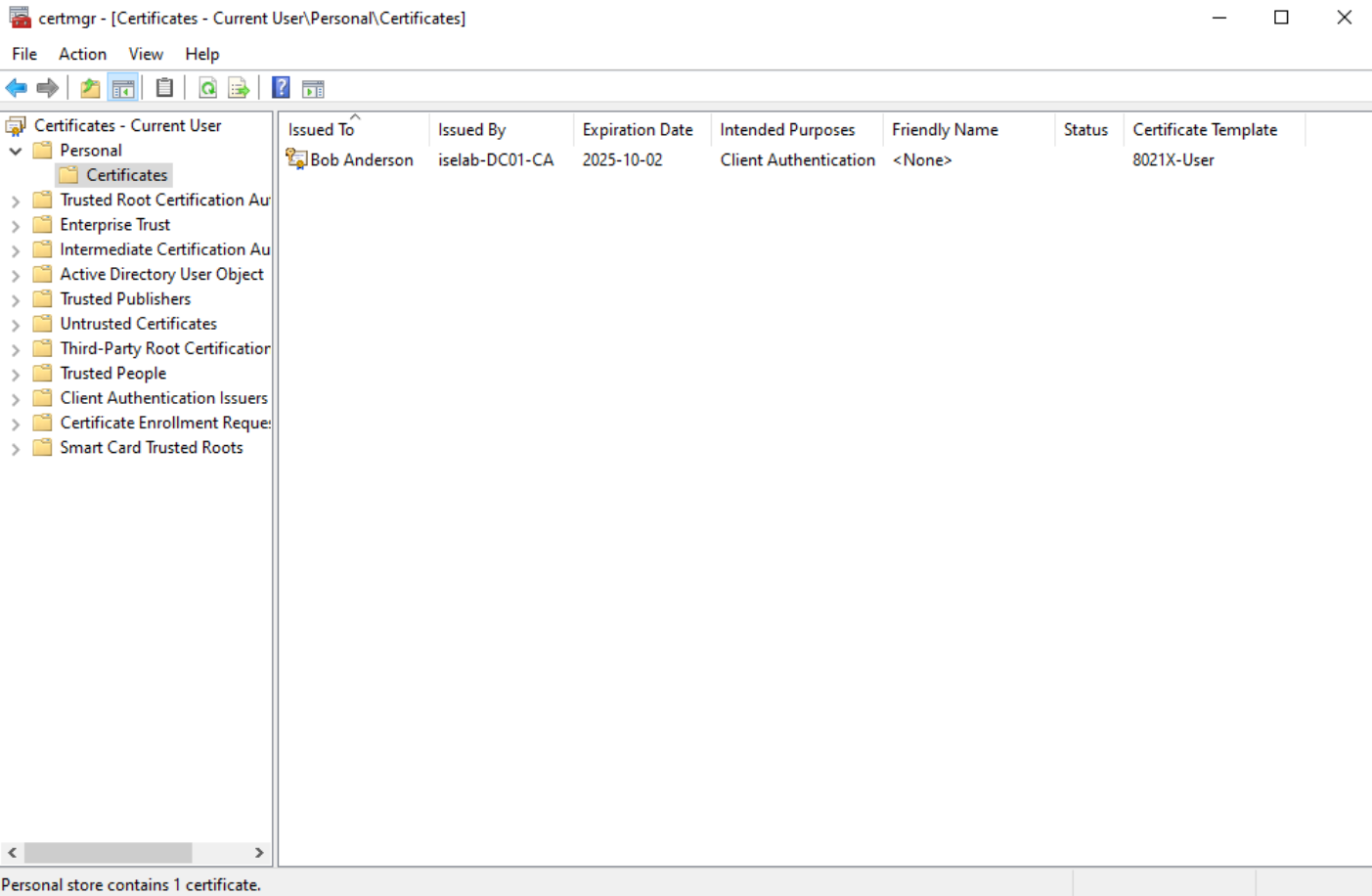
After logging in, certificates will be created for both the user and computer. We can verify this on the CA:
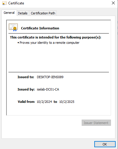
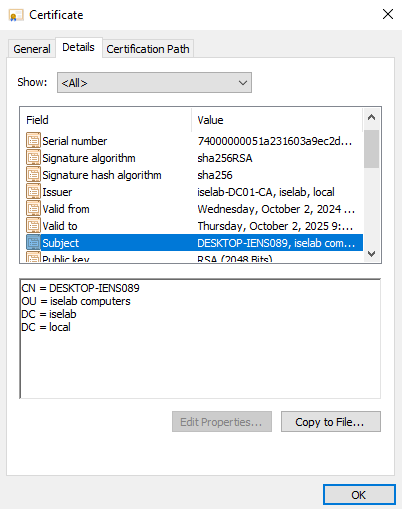
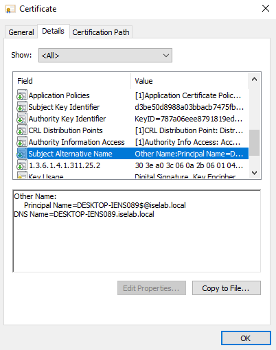
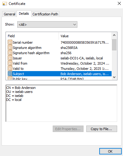
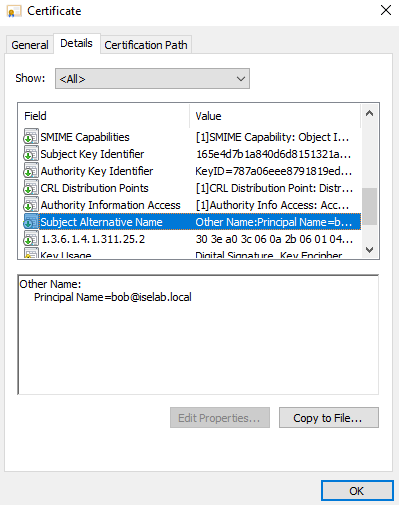
You can also use the cert manager on the client to verify the certificates. Below is the computer certificate:
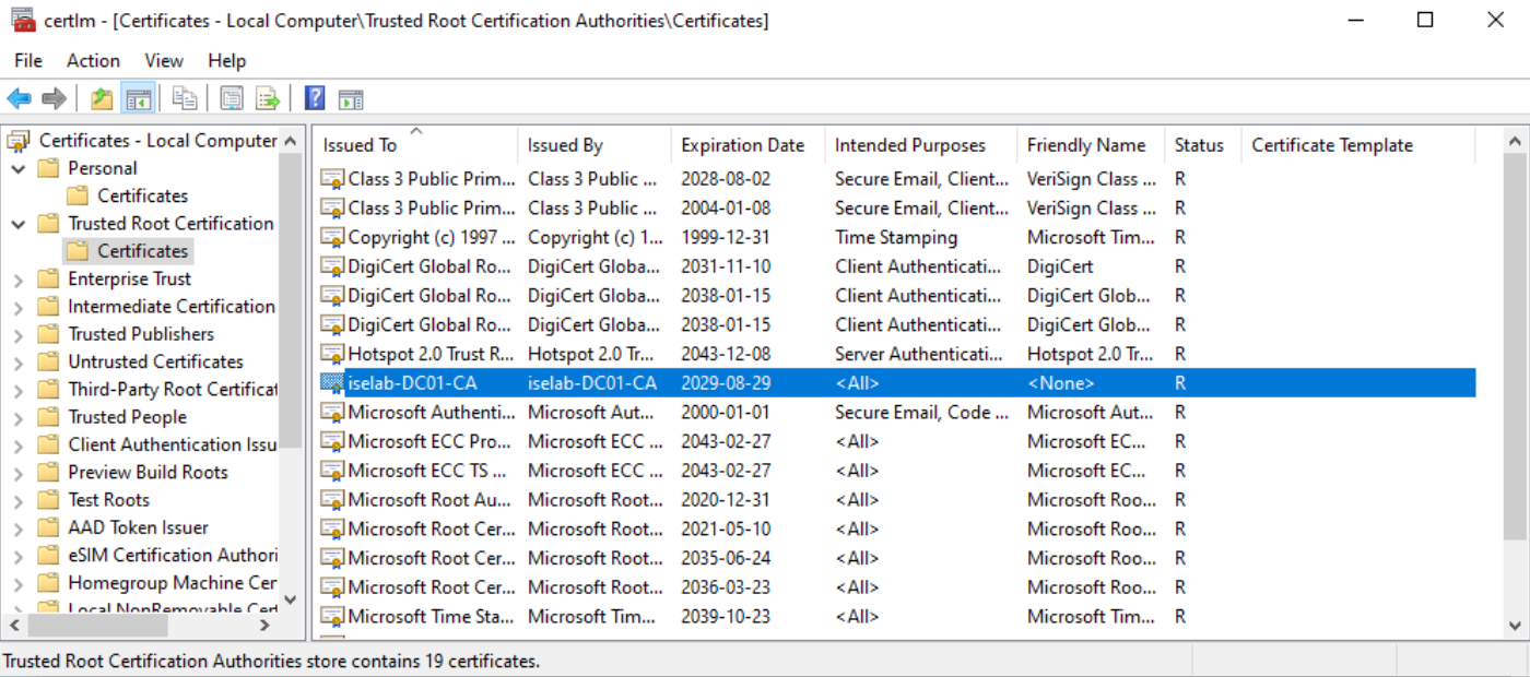
The trusted root CA for computer certificates:
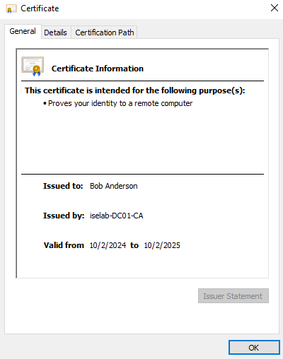
The user certificate:
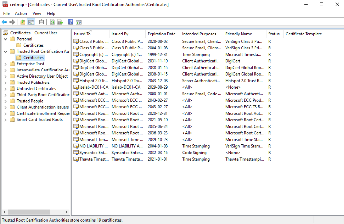
Trusted root CA for user certs:
Before I got my setup working, I had to do Continue reading
By default, users and computers will be placed in containers in AD. These containers don’t support the use of GPOs, which is one of the reasons to create OUs to hold the objects instead. To verify what the default user and computer container is, we’ll leverage Powershell. First, we’ll check the computers container:
PS C:\Users\Administrator> Get-ADDomain | select computerscont*
ComputersContainer
------------------
CN=Computers,DC=iselab,DC=local
Then, we’ll check the users container:
PS C:\Users\Administrator> Get-ADDomain | select userscont*

UsersContainer
--------------
CN=Users,DC=iselab,DC=local
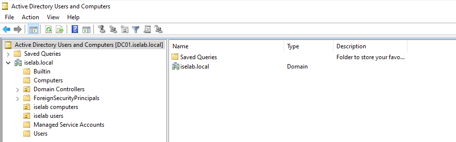
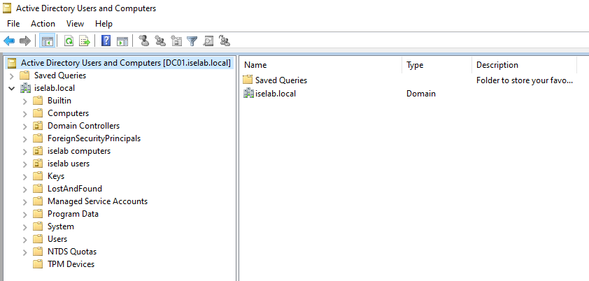
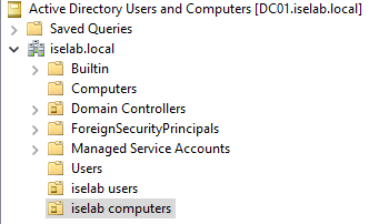
Now, in my lab I have created iselab users and iselab computers where I want the user- and computer objects to be placed:
We’re going to user some Powershell to modify where the user- and computer objects get placed, but first we’ll get the Distinguished Name (DN) of these OUs. To do this, we’ll first have to enable Advanced Features under View:
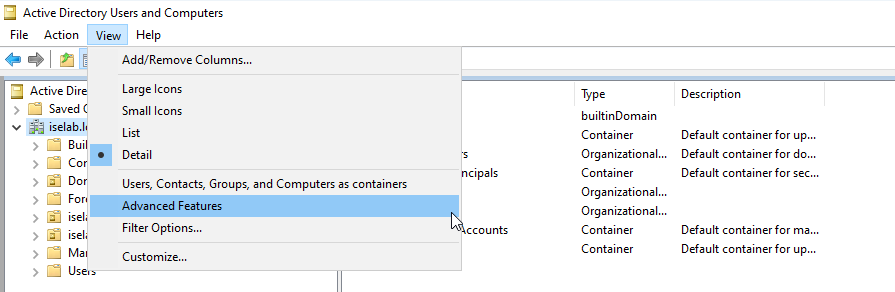
This will display some additional containers:
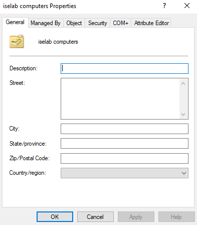
Now right click the OU, such as iselab computers, and select Properties:
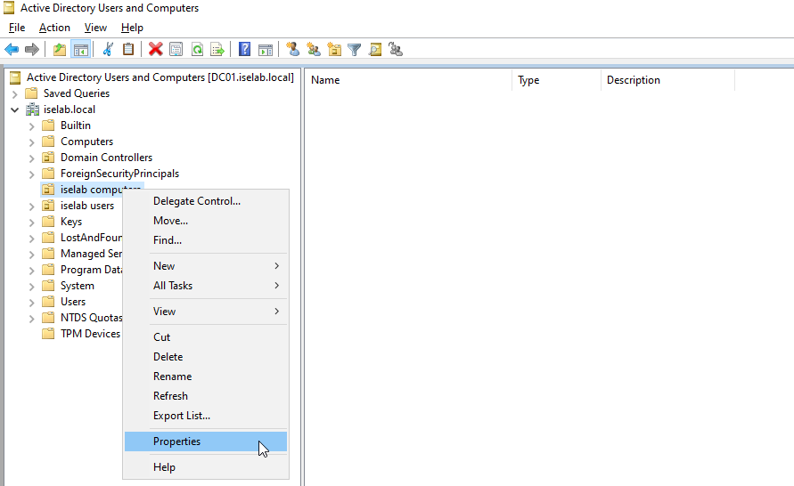
This will display the following window:
Now go to Attribute Editor tab, double click distinguishedName and right click and select Copy:
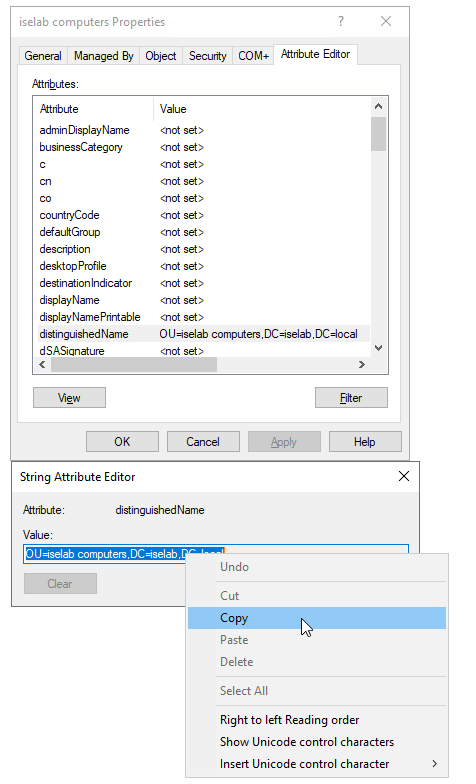
Then, we’ll user Powershell to redirect to this OU:
PS C:\Users\Administrator> redircmp "OU=iselab computers,DC=iselab,DC=local"
Redirection was successful.
Let’s verify what Continue reading
The use of Group Policy Objects (GPO) can be really powerful in a Windows environment. In this post we’re going to leverage GPO to distribute certificates to the user and computer as well as enabling the 802.1X supplicant.
First, let’s see if there are any certificates on the Windows 10 VM in my lab:
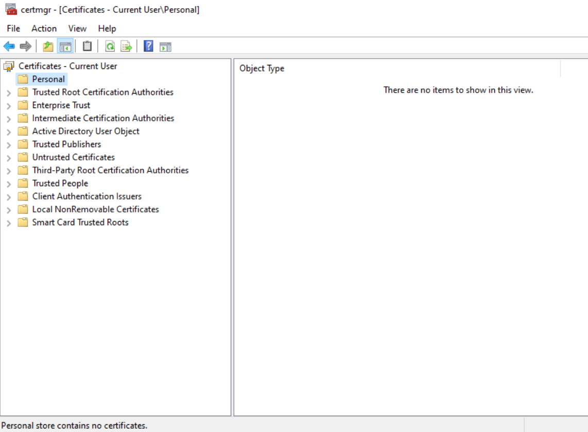
Currently, there are no certificates present on the VM. It has also not been joined to the domain.
First, open the GPO app:
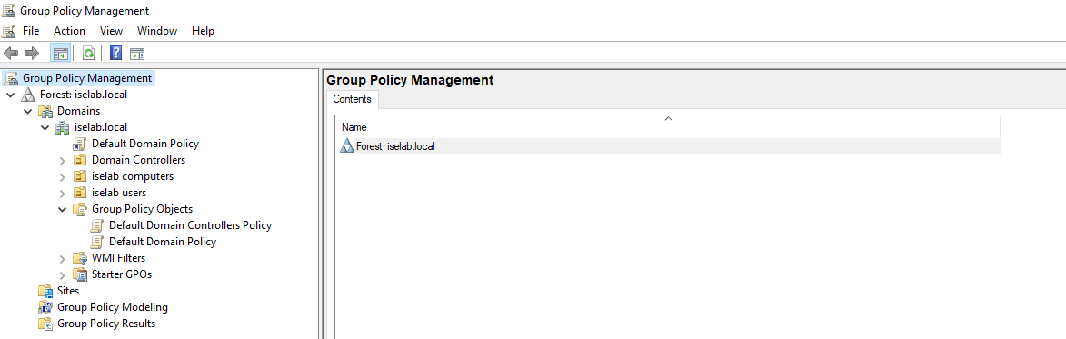
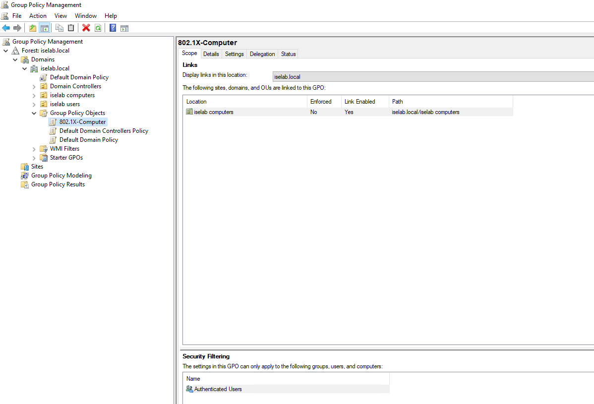
There’s a default domain policy that can be used, but I’m going to create new policies, one for users, and one for computers. First, let’s create a policy for computers. I’m going to right click my computer OU, named iselab computers, and then select Create a GPO in this domain, and Link it here…:
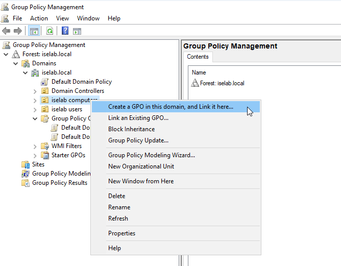
Give the GPO a name:
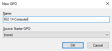
The GPO has been created:
Right click the GPO and select Edit…:
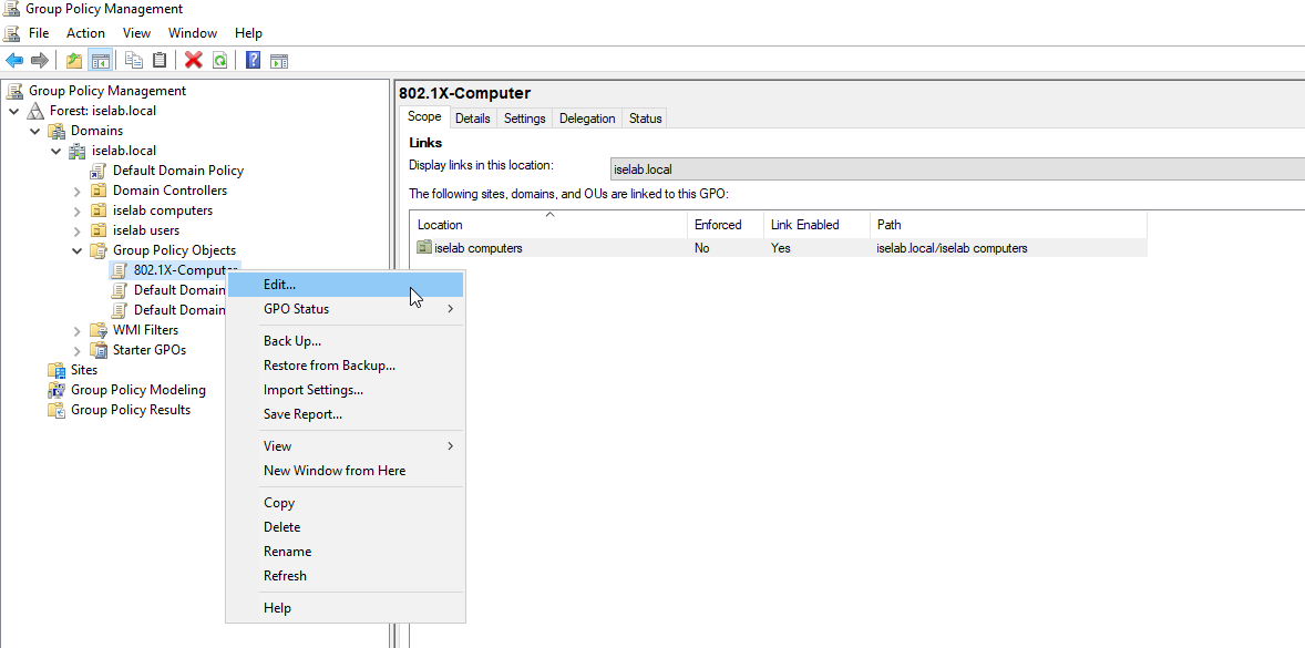
The GPO Editor window opens:
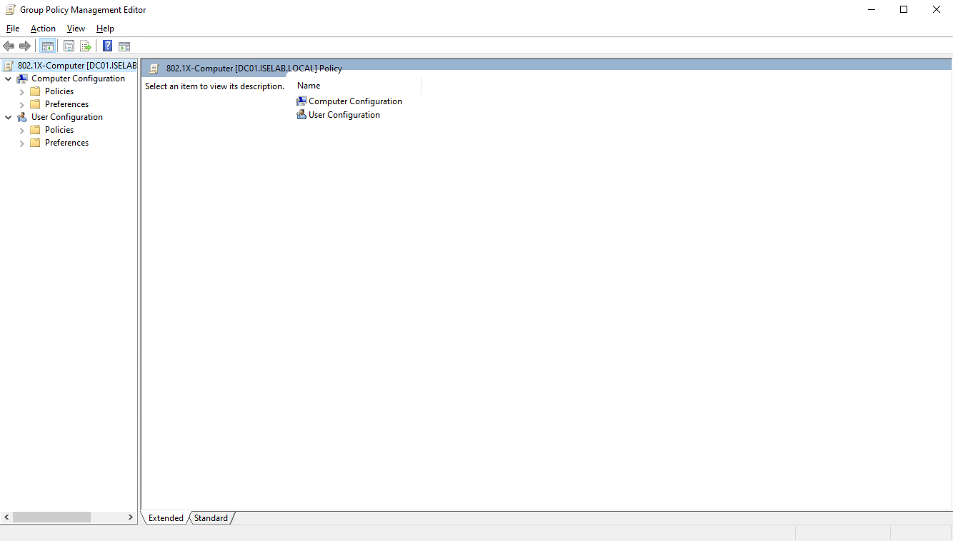
Then we’re going to navigate to Computer Configuration -> Policies -> Windows Settings -> Security Settings -> Public Key Policies and select Certificate Services Client – Auto Enrollment and then Properties:
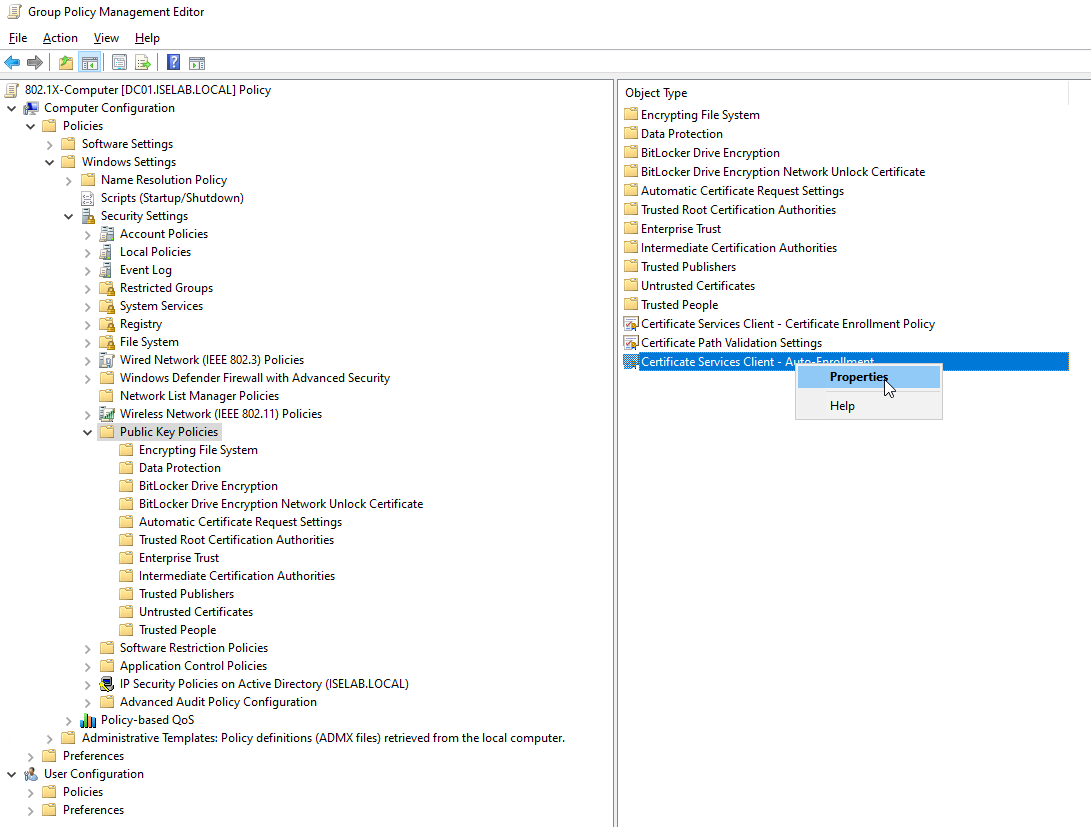
A new window opens up:
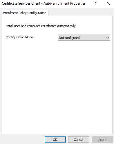
Change the Configuration Model to Enabled and Continue reading
Most ISE deployments use a join to Active Directory to be able to query AD groups, perform user lookups, etc. In this post, I’ll join my ISE lab server to AD. First I’m going to create two OUs in my AD, one for users and one for computers. Why not use the default ones? They are containers, not OUs, which means you can’t apply GPOs to them. Additionally, it makes for cleaner separation from the built-in accounts and allows for applying policies that won’t affect them. I’m creating two OUs:
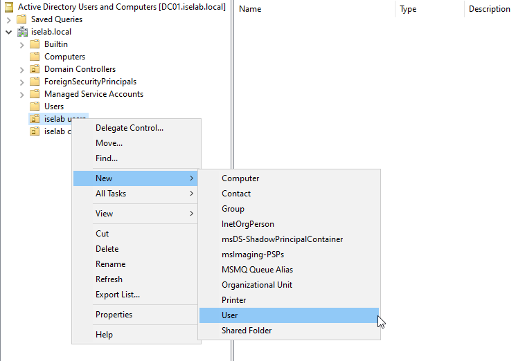
This is done by going to Active Directory Users and Computers, then right clicking the AD domain and selecting New -> Organizational Unit:
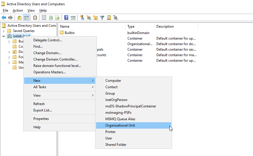
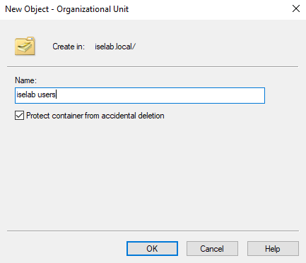
Give the OU a name and then click OK:
Repeat for the computers OU. You should now be able to see the OUs:
I’m going to create a user named Bob that I’ll be using to test login later. Right click the users OU and then select New -> User:
Enter the name and logon name:
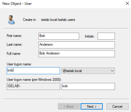
Click Next. Enter a password for the user. As this is a lab, I won’t require that the user changes the password and the Continue reading
When ISE is installed, all the certificates used for different services such as EAP, Admin portal, etc., are self signed. Below is a short summary of the certificates that ISE uses:
The certificates can be seen by going to Administration -> System -> Certificates:
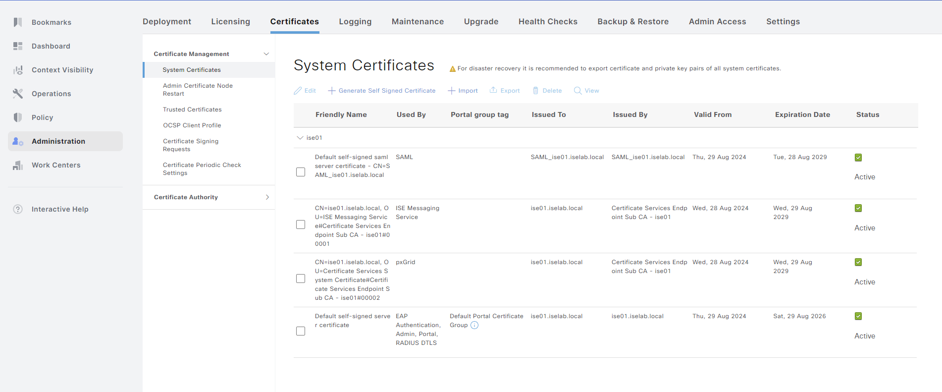
A certificate can be viewed by selecting the checkbox and clicking View:
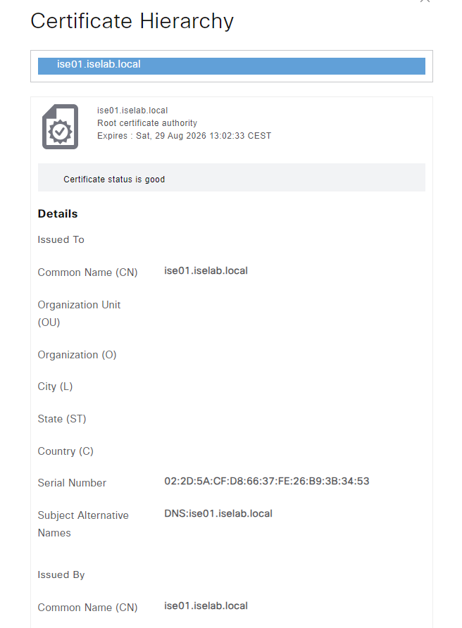
Self-signed certificates aren’t good. Certificates should be signed by a trusted CA. That could be a public root CA, or more commonly, especially for labs, an internal CA. Before such a certificate can be installed, ISE must be configured to trust that CA. This is done by importing the root CA certificate. I’ll download the certificate from the web service on the ADCS server. The web service is reachable on https:://<IP of ADCS server>/certsrv/. Click Download a CA certificate, certificate chain or CRL:

On the next page, change to Base 64 and then click Download CA certificate:
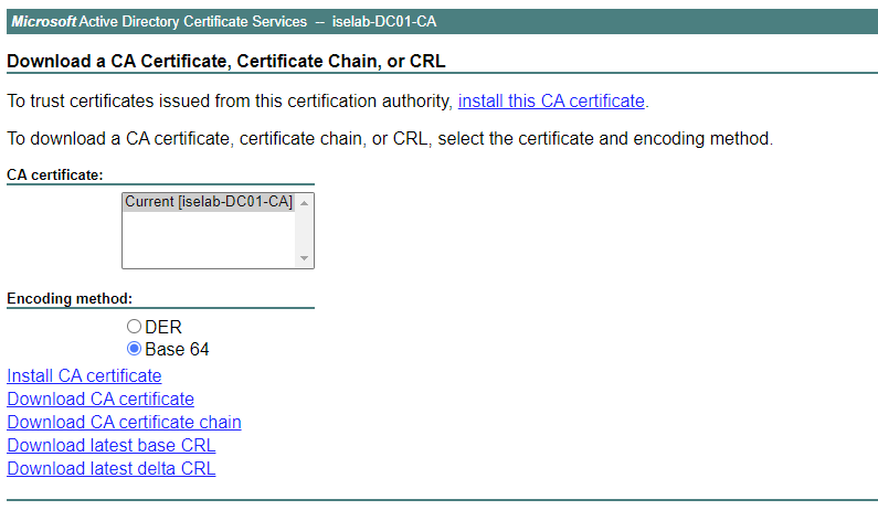
The file is downloaded Continue reading
This post describes how to install a Cisco ISE evaluation VM for labbing. The VM will run for 90 days, providing a full feature set for up to 100 endpoints.
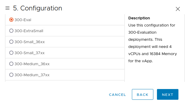
Start by downloading the software. I’ll be using an OVA as I’m going to run my VM on ESX:

Deploy the OVA and select Eval version:
Power on the VM. When the VM boots, the following prompt is shown:

Type setup and press enter:
You will have to configure the hostname, IP address, name server, and so on:
Press 'Ctrl-C' to abort setup
Enter hostname[]: ise01
Enter IP address []: 192.168.128.102
Enter IP netmask []: 255.255.255.0
Enter IP default gateway []: 192.168.128.1
Do you want to configure IPv6 address? Y/N [N]: N
Enter default DNS domain []: iselab.local
Enter primary nameserver []: 192.168.128.100
Add secondary nameserver? Y/N [N]: N
Enter NTP server[time.nist.gov]: ntp.netnod.se
Add another NTP server? Y/N [N]: N
Enter system timezone[UTC]: CET
Enable SSH service? Y/N [N]: Y
Enter username [admin]: admin
Enter password:
Enter password again:
Bringing up the network interface...
The installation will take some time…
When the installation Continue reading
In my ISE lab I’m going to be using EAP-TLS and TEAP, which means I’ll be needing user and computer certificates. The goal is to be able to enable the 802.1X supplicant via GPO and to distribute certificates automatically without requiring any user input. Another post will cover GPO, in this post I’ll cover creating the certificate templates in ADCS.
When opening the CA app, there are a number of templates provided by default:
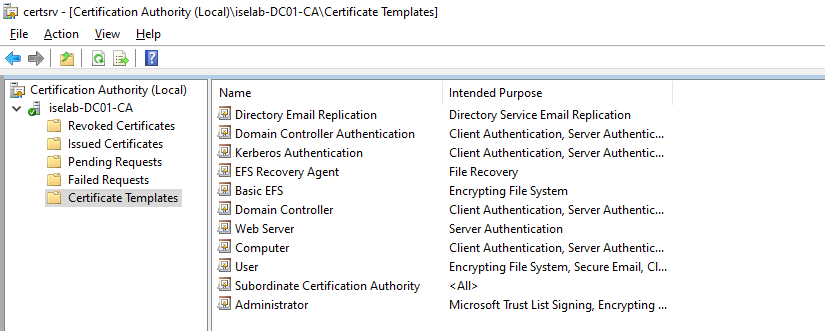
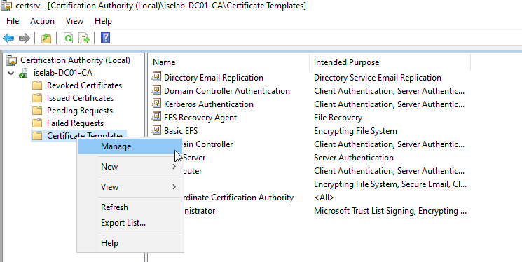
There are already templates for User and Computer, but it’s better to leave the default templates alone and create new ones. First, we’ll create a template for user certificates. Start by right clicking Certificate Templates and selecting Manage:
Then we’re going to right click the User template and select Duplicate Template:
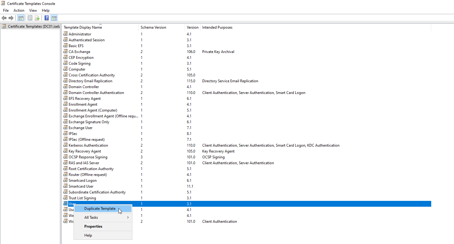
This is going to open up a new window with properties of the template:
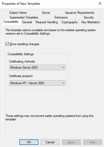
Go to General and give the template a name:
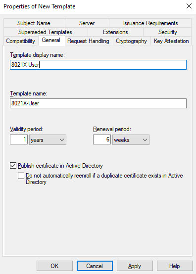
Don’t select the Do not automatically reenroll option or it won’t be possible to renew certs before they expire.
Then go to Request Handling. We’re going to uncheck the Allow private key to be exported option as this is considered more secure:
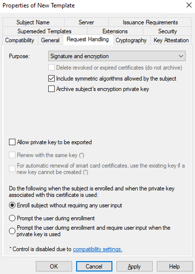
Make sure Enroll subject without requiring any Continue reading
 Deployment Type: Standalone
Choose a password for your CA keys and first provisioner.
Deployment Type: Standalone
Choose a password for your CA keys and first provisioner.