Cisco vPC in VXLAN/EVPN Network – Part 5 – Potential Pitfalls
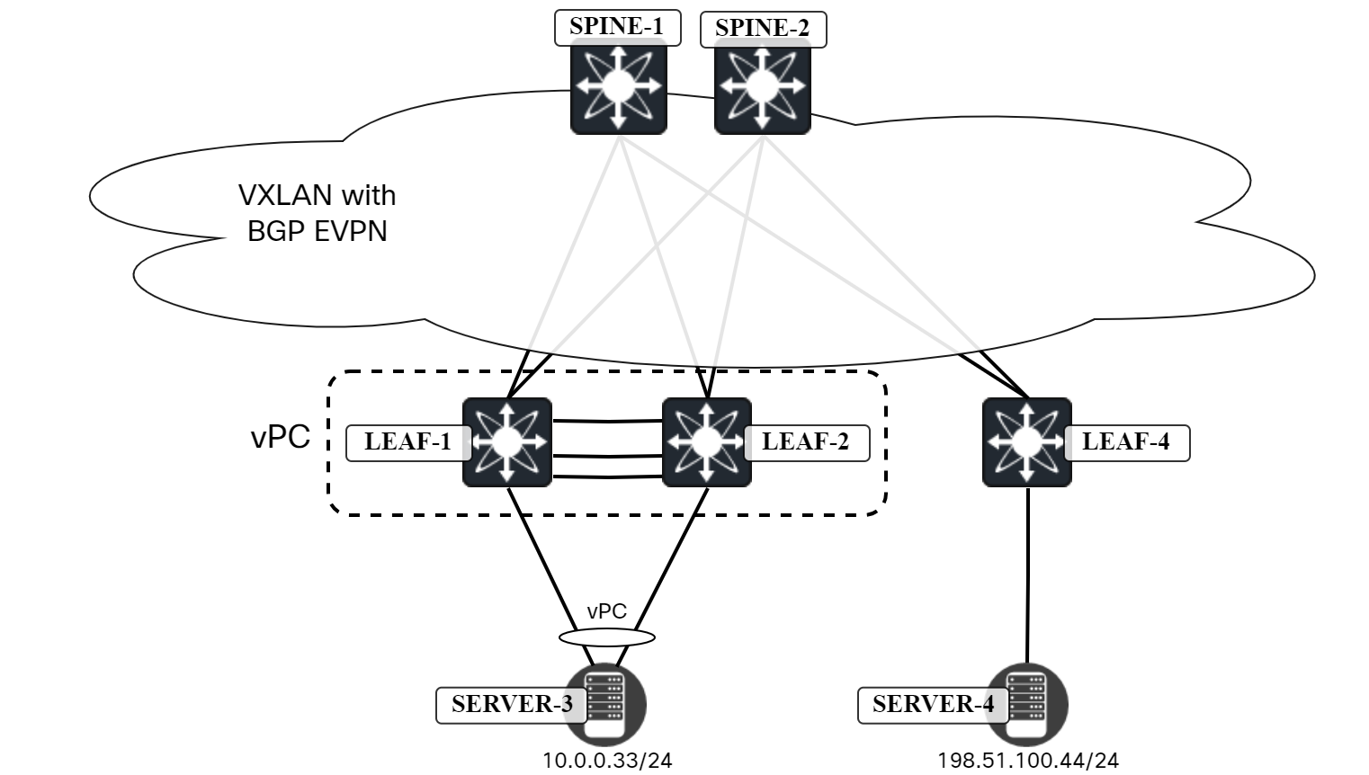
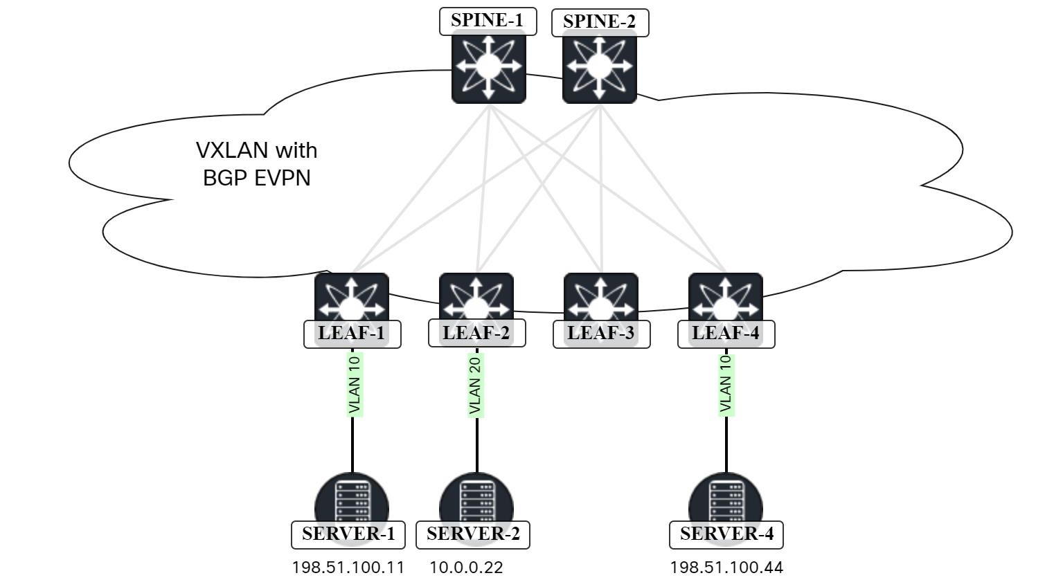
Like I hinted at in an earlier post, there are a some failure scenarios you need to consider for vPC. The first scenario we can’t really do much with, but I’ll describe it anyway. The topology is the one below:
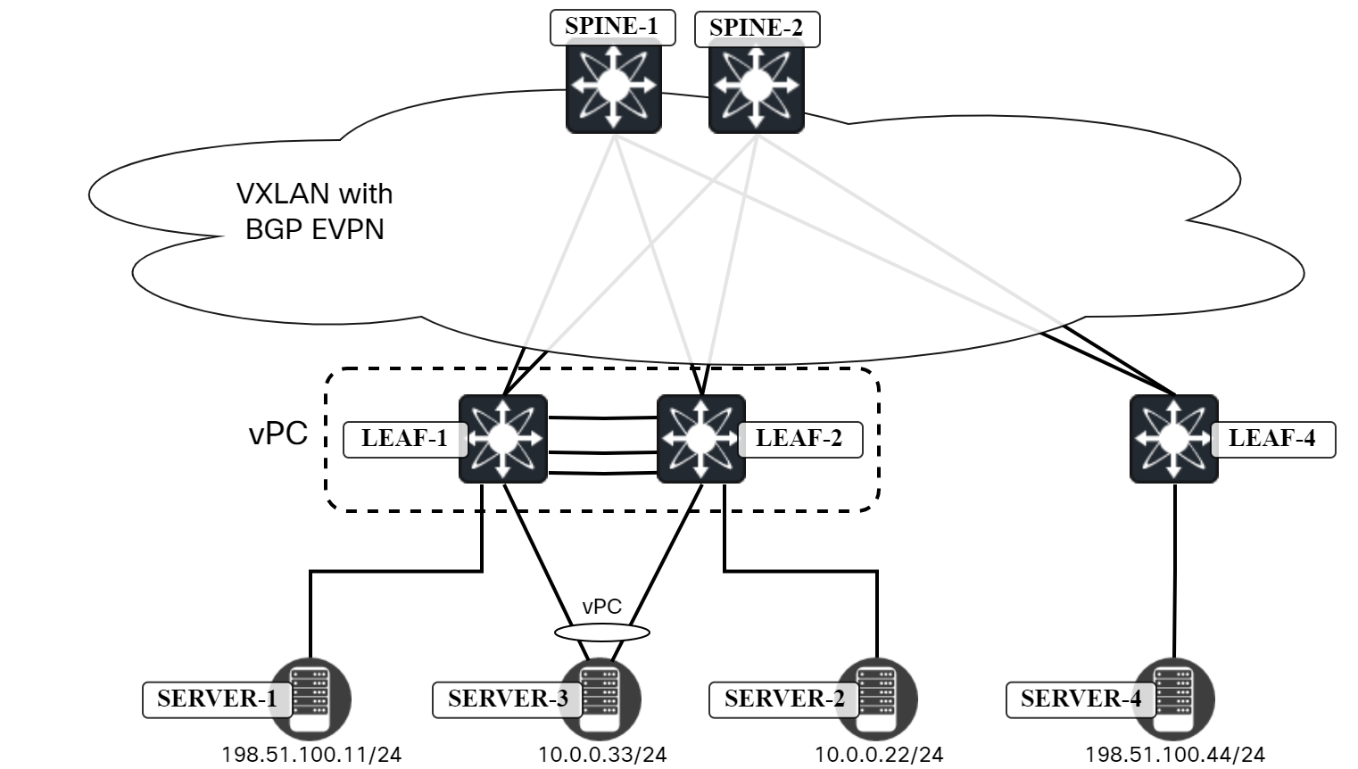
Server4 needs to send a packet to Server1. Leaf4 has the following routes for 198.51.100.11:
Leaf4# show bgp l2vpn evpn 198.51.100.11
BGP routing table information for VRF default, address family L2VPN EVPN
Route Distinguisher: 192.0.2.3:32777
BGP routing table entry for [2]:[0]:[0]:[48]:[0050.56ad.8506]:[32]:[198.51.100.11]/272, version 13677
Paths: (2 available, best #2)
Flags: (0x000202) (high32 00000000) on xmit-list, is not in l2rib/evpn, is not in HW

  Path type: internal, path is valid, not best reason: Neighbor Address, no labeled nexthop
  AS-Path: NONE, path sourced internal to AS
    203.0.113.12 (metric 81) from 192.0.2.12 (192.0.2.2)
      Origin IGP, MED not set, localpref 100, weight 0
      Received label 10000 10001
      Extcommunity: RT:65000:10000 RT:65000:10001 SOO:203.0.113.12:0 ENCAP:8
          Router MAC:00ad.e688.1b08
      Originator: 192.0.2.3 Cluster list: 192.0.2.2

  Advertised path-id 1
  Path type: internal, path is valid, is best path,  Continue reading
Cisco vPC in VXLAN/EVPN Network – Part 4 – Fabric Peering
Like I mentioned in a previous post, normally leafs don’t connect to leafs, but for vPC this is required. What if we don’t want to use physical interfaces for this interconnection? This is where fabric peering comes into play. Now, unfortunately my lab, which is virtual, does not support fabric peering so I will just introduce you to the concept. Let’s compare the traditional vPC to fabric peering, starting with traditional vPC:
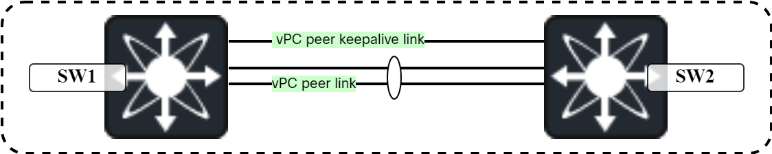
The traditional vPC has the following pros and cons:
- Pros:
- No dependency on other devices for peer link and peer keepalive link.
- No contention for bandwidth on interfaces as they are dedicated.
- This also means no QoS configuration is required.
- Intent of configuration is clear with dedicated interfaces.
- Cons:
- Requires dedicated interfaces that could be used for something else.
- Interfaces have a cost, both from perspective of buying the switch, but also SFPs.
Now let’s compare that to fabric peering:
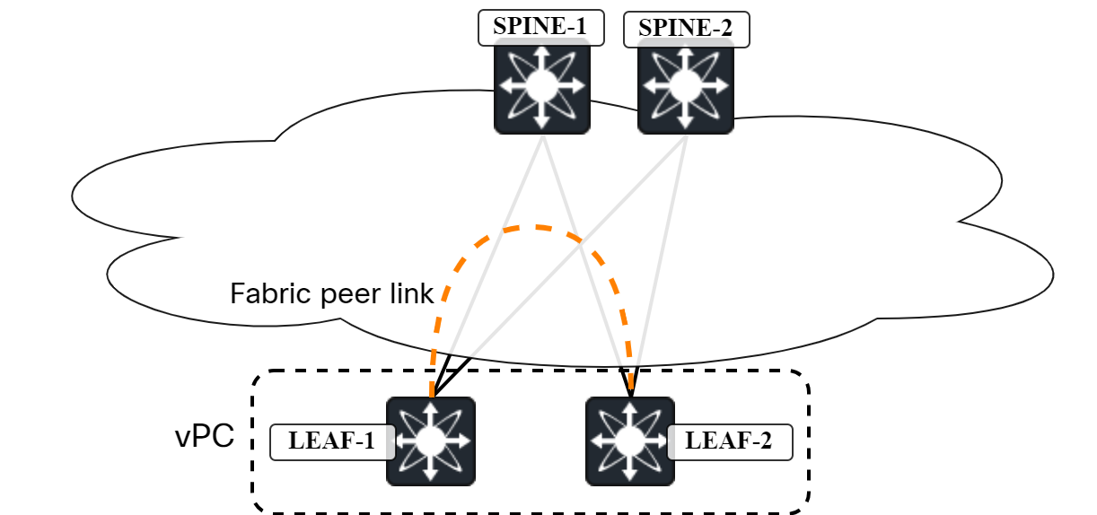
Fabric peering has the following pros and cons:
- Pros:
- No dedicated interfaces required.
- Thus reducing cost.
- Resiliency as there are multiple paths between the two switches.
- Cons:
- Dependency to other devices.
- Dependency to underlay.
- Contention for bandwidth with other traffic.
- May require QoS.
- May be more difficult to Continue reading
Cisco vPC in VXLAN/EVPN Network – Part 3 – Verifying Connectivity
The following topology is used:

We want to verify connectivity and traffic flow towards:
- Gateway of Server3.
- Server1.
- Server2.
- Server4.
Let’s start with the gateway. The gateway is at 10.0.0.1 and has a MAC address of 0001.0001.0001:
server3:~$ ip neighbor | grep 10.0.0.1
10.0.0.1 dev bond0 lladdr 00:01:00:01:00:01 STALE
This is an anycast gateway MAC. When initiating a ping towards 10.0.0.1, it can go to either Leaf1 or Leaf2. I will run Ethanalyzer on the switches to confirm which one is receiving the ICMP Echo Request:
Leaf1# ethanalyzer local interface inband display-filter "icmp" limit-captured-frames 0
Capturing on 'ps-inb'

Leaf2# ethanalyzer local interface inband display-filter "icmp" limit-captured-frames 0
Capturing on 'ps-inb'
Then initiate ping from Server3:
server3:~$ ping 10.0.0.1
PING 10.0.0.1 (10.0.0.1) 56(84) bytes of data.
64 bytes from 10.0.0.1: icmp_seq=1 ttl=255 time=1.19 ms
64 bytes from 10.0.0.1: icmp_seq=2 ttl=255 time=1.29 ms
^C
--- 10.0.0.1 ping statistics ---
2 packets transmitted, 2 received, 0% packet loss, time 1001ms
rtt min/avg/max/mdev = 1.192/1.242/1.292/0.050 ms
Cisco vPC in VXLAN/EVPN Network – Part 2 – Configuring vPC
When building leaf and spine networks, leafs connect to spines, but leafs don’t connect to leafs, and spines don’t connect to spines. There are exceptions to this and vPC is one of those exceptions. The leafs that are going to be part of the same vPC need to connect to each other. There are two ways of achieving this:
- Physical interfaces.
- Fabric peering.
We will first use physical interfaces and then later remove that and use fabric peering. Now, my lab is virtual so take physical with a grain of salt, but they will be dedicated interfaces. The following will be required to configure vPC:
- Enable vPC.
- Enable LACP.
- Create vPC domain.
- Create a VRF for the vPC peer keepalive.
- Configure the interface for vPC peer keepalive.
- Configure the vPC peer keepalive.
- Configure the vPC peer link interfaces.
- Configure the vPC peer link.
This is shown below:

The vPC is now up:
Leaf1# show vpc
Legend:
                (*) - local vPC is down, forwarding via vPC peer-link

vPC domain id                     : 1
Peer status                       : peer adjacency formed ok
vPC keep-alive status             : peer is alive
Configuration consistency status  : success
Per-vlan consistency status       : success
Type-2 consistency status         : success
 Continue reading
Cisco vPC in VXLAN/EVPN Network – Part 1 – Anycast VTEP
Many vendors offer MLAG features, that is, the ability to form a PortChannel (some vendors call it trunk or bond) towards two separate devices. In this post, I will cover the following:
- Briefly describe vPC in a traditional network.
- Describe vPC in a VXLAN/EVPN network.
- Configure leaf switches to support vPC.
- Setup of Ubuntu Linux host to bond two interfaces and use LACP.
- Verification of the setup.
Traditional vPC
On Cisco Nexus switches, virtual Port Channel (vPC) has been a highly used feature for many years. It has been used towards other network devices such as firewalls, routers, and switches, but also towards hosts running hypervisors such as ESX.
As opposed to other technologies such as Virtual Switching System (VSS) or StackWise Virtual, it does not require the two switches to become one to provide the ability to do MLAG. Instead, the two devices appear as one in PDUs such as LACP, STP, and IGMP, by using a vPC system MAC address as the source MAC. With MLAG features, the two switches need to verify the other is alive and also synchronize state and perform consistency checking. This is done by connecting them with a vPC peer keepalive link, and Continue reading
CCNA 200-301 Updated To Version 1.1
Cisco is updating the Cisco Certified Network Associate (CCNA) exam to version 1.1. In the past, Cisco only did major updates to their exams. Since then, they have moved to doing more frequent and minor updates, in a more agile fashion. Before going in to the changes, let’s answer some common questions that are covered in Cisco’s FAQ:
Why is the CCNA being updated?
Cisco regularly performs reviews of their exams. Exams get updated to clarify exam topics, introduce new ones, and phase out outdated products and solutions.
What is being added?
New topics include generative AI, cloud network management, and machine learning.
When can candidates register for CCNA v1.1?
Registration begins on August 20, 2024.
What if I’m already studing for CCNA v1.0?
Complete your study and take the CCNA v1.0 exam.
What percentage of the exam is being updated?
Approximately 10% of the exam is updated.
When is the last day to test for CCNA v1.0?
The last day of testing for CCNA v1.0 is August 19, 2024.
So what is being changed? The different domains and their percentages is not changing. The domains and their percentage remain as:
- 1.0 Network Continue reading
1000BASE-T Part 4 – Link Down Detection
In the previous three parts, we learned about all the interesting things that go on in the PHY with scrambling, descrambling, synchronization, auto negotiation, FEC encoding, and so on. This is all essential knowledge that we need to have to understand how the PHY can detect that a link has gone down, or is performing so badly that it doesn’t make sense to keep the link up.
What Does IEEE 802.3 1000BASE-T Say?
The function in 1000BASE-T that is responsible for monitoring the status of the link is called link monitor and is defined in 40.4.2.5. The standard does not define much on what goes on in link monitor, though. Below is an excerpt from the standard:
Link Monitor determines the status of the underlying receive channel and communicates it via the variable
link_status. Failure of the underlying receive channel typically causes the PMA’s clients to suspend normal
operation.
The Link Monitor function shall comply with the state diagram of Figure 40–17.
The state diagram (redrawn by me) is shown below:
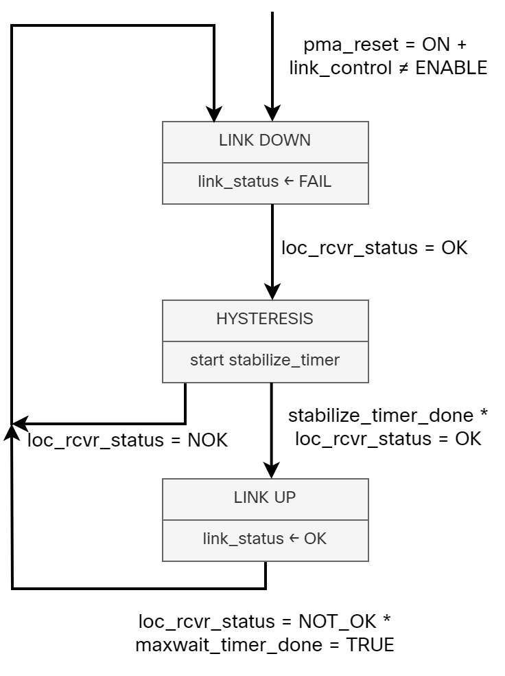
While 1000BASE-T leaves what the PHY monitors in link monitor to the implementer, there are still some interesting variables and timers that you should be Continue reading
Troubleshooting vPC in My Virtual Lab
I’m preparing a blog post on setting up vPC in a VXLAN/EVPN environment. While doing so, I ran into some issues. Rather than simply fixing them, I wanted to share the troubleshooting experience as it can be useful to see all the things I did to troubleshoot, including commands, packet captures, etc., and learn a little about virtual networking. As always, thanks to Peter Palúch for providing assistance with the process.
Topology
The following topology implemented in ESX is used:
Background
I had just configured the vPC peer link and vPC peer link keepalive. I verified that the vPC was functional with the following command:
Leaf1# show vpc
Legend:
                (*) - local vPC is down, forwarding via vPC peer-link

vPC domain id                     : 1
Peer status                       : peer adjacency formed ok
vPC keep-alive status             : peer is alive
Configuration consistency status  : success
Per-vlan consistency status       : success
Type-2 consistency status         : success
vPC role                          : primary
Number of vPCs configured         : 1
Peer Gateway                      : Disabled
Dual-active excluded VLANs        : -
Graceful Consistency Check        : Enabled
Auto-recovery status              : Disabled
Delay-restore status              : Timer is off.(timeout = 30s)
Delay-restore SVI status          : Timer is off.(timeout =  Continue reading
1000BASE-T Part 3 – Autonegotiation
In this post, we’ll take a closer look at auto negotiation. Auto negotiation has the following characteristics:
- It is required to be supported.
- Transmits capabilities for speed/duplex.
- Negotiates Energy Efficient Ethernet (EEE) capabilities.
- Determines the leader/follower relationship on the link.
- Needed for PHY Control, a PMA subfunction.
- Performed when initializing the link.
- Auto-MDIX.
The Auto Negotiation transmitter and receiver is actually a separate system in its own right. In multi-speed PHY devices, auto negotiation is used to select the highest speed that both sides of the link are capable of, before the link is trained. However, it is important to understand that auto negotiation is not optional to be supported, but the standard does not require it to be implemented (thanks to Eric Peterson for clarifying this). A leader and follower must be decided so that clock synchronization can take place. Without auto negotiation, this would have to be manually configured. On some devices it is possible to configure speed on 1000BASE-T interface. However, this does normally not disable auto negotation, but rather limit what capabilities get advertised.
Auto negotiation is performed using Fast Link Pulses (FLP). Historically, 10BASE-T used Link Test Pulse (LTP) to verify the integrity Continue reading
1000BASE-T Part 2 – Deepdive
In 1000BASE-T Part 1, we reviewed the layers and what their purpose is. Now we’re going to go much deeper into the layers that relate to the PHY, which is PCS, PMA, and Autonegotiation. First though, let’s review the objectives of 1000BASE-T:
- Support the CSMA/CD MAC.
- Comply with specifications for GMII (Clause 35).
- Support 1000 Mbit/s repeater (Clause 41).
- Provide line transmission support full and half duplex operation.
- Meet or exceed FCC Class A/CISPR or better operation.
- Support operation over 100 meters of copper balanced cabling (defined in 40.7).
- Bit Error Ratio less than or equal to 10^-10.
- Support Auto negotiation (Clause 28).
How does 1000BASE-T achieve a bandwidth of 1000 Mbit/s? As you probably know, the twisted pair cable consists of four pairs, eight wires in total, where transmit and receive are separated to achieve full duplex operation:
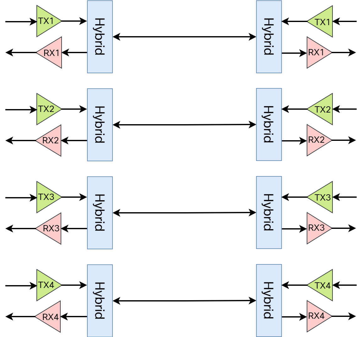
The meaning of hybrid in this context is that transmit and receive is performed on the same pair. Every pair is capable of 250 Mbit/s data rate, for a total of 1000 Mbit/s. As PAM-5 encoding is used (more on this later), the baud rate is 125 MHz. This means that the PHY receives 8-bit words to send every Continue reading
1000BASE-T Part 1 – Introduction
How does Ethernet detect that a link goes down? This, what I thought was a simple question, I asked myself a couple of weeks ago. I realized I didn’t have a very good answer. I realized I had more to learn about Ethernet and the physical layer and so does pretty much the entire networking industry. Through the graceful help of Peter Jones at Cisco, I got in touch with George Zimmerman, an independent professional with a PhD in electrical engineering, a history of teaching at Caltech, and that works within the IEEE on different standards. To answer my initial question, we first need to understand more about Ethernet, and especially the physical layer. As every version of Ethernet has slightly different PHY, I will be covering 1000BASE-T. This will be covered in a series of posts, this being the first.
Going back to the OSI model, most roles in networking puts the focus on layers two to four:
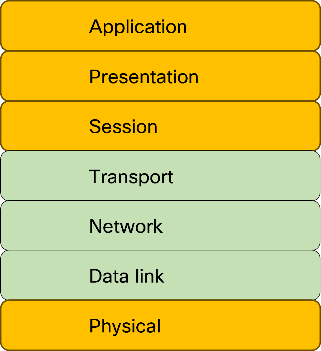
This is natural as most of our work relates to these layers.
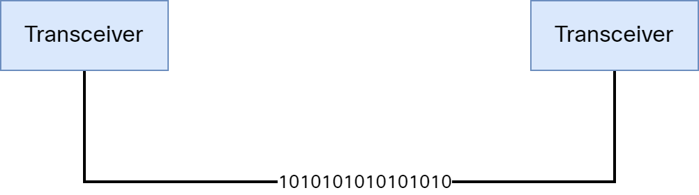
When we think of two hosts communicating, we imagine that the transceivers connect to each other and that there are ones and zeroes traveling across the cable:
How Anycast VTEP Broke My Lab And What I Learned
I’m preparing a massive blog post on vPC in the context of VXLAN/EVPN and while doing so I accidentally broke my lab. What a great learning experience! I thought I would share it with you and how to perform troubleshooting of this scenario.
My topology looks like this:
Before I made any changes, there was full connectivity between these hosts, meaning that both bridging and routing was working. I then changed the loopback1 (NVE source interface) configuration of Leaf-1 and Leaf-2 to add a secondary IP. This was the initial configuration:
! Leaf-1
interface loopback1
  description VTEP
  ip address 203.0.113.1/32
  ip router ospf UNDERLAY area 0.0.0.0
  ip pim sparse-mode
! Leaf-2
interface loopback1
  description VTEP
  ip address 203.0.113.2/32
  ip router ospf UNDERLAY area 0.0.0.0
  ip pim sparse-mode
This then changed to:
! Leaf-1
interface loopback1
  description VTEP
  ip address 203.0.113.1/32
  ip address 203.0.113.12/32 secondary
  ip router ospf UNDERLAY area 0.0.0.0
  ip pim sparse-mode
! Leaf-2
interface loopback1
  description VTEP
  ip address 203.0.113.2/32
  ip address 203.0.113.12/32 secondary
  ip router ospf UNDERLAY area 0.0.0.0
  ip pim  Continue reading
Routed Packet Walk in VXLAN/EVPN Network
In a previous post, I walked through how a packet gets bridged in a VXLAN/EVPN network. In this post, I’ll go through how a packet gets routed, that is, packet from one VNI to another VNI. The following topology will be used:
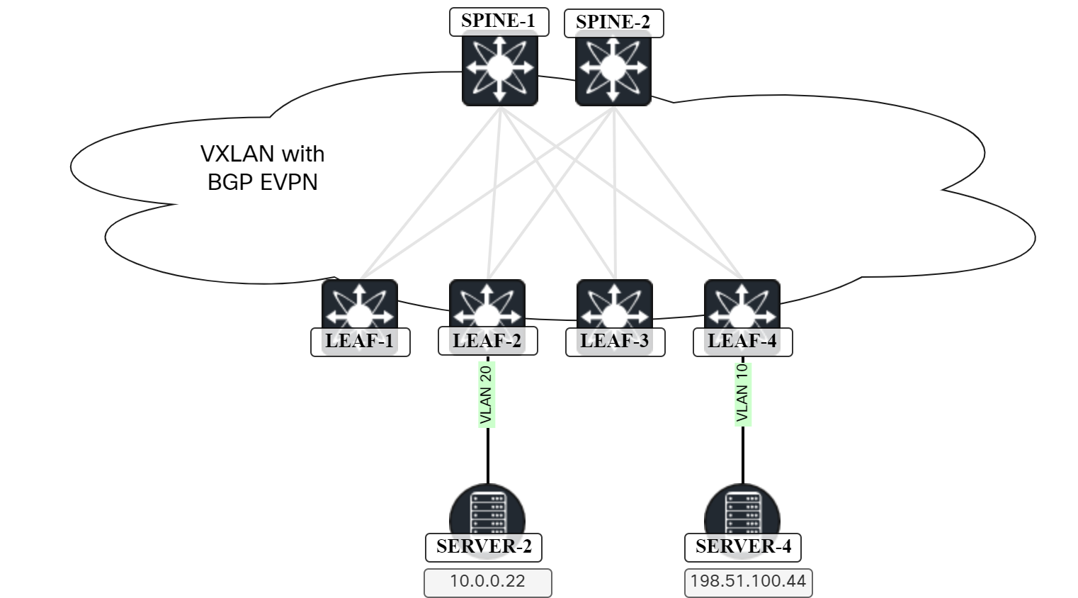
The lab has the following characteristics:
- OSPF in the underlay.
- Ingress replication for BUM traffic through the use of EVPN.
- ARP suppression is enabled.
Server-2 initiates a ping towards Server-4:
Frame 562: 98 bytes on wire (784 bits), 98 bytes captured (784 bits) on interface ens257, id 4
Ethernet II, Src: 00:50:56:ad:f4:8d, Dst: 00:01:00:01:00:01
Internet Protocol Version 4, Src: 10.0.0.22, Dst: 198.51.100.44
Internet Control Message Protocol
    Type: 8 (Echo (ping) request)
    Code: 0
    Checksum: 0xd745 [correct]
    [Checksum Status: Good]
    Identifier (BE): 17 (0x0011)
    Identifier (LE): 4352 (0x1100)
    Sequence Number (BE): 1 (0x0001)
    Sequence Number (LE): 256 (0x0100)
    [Response frame: 563]
    Timestamp from icmp data: Mar  3, 2024 08:38:35.804470000 Romance Standard Time
    [Timestamp from icmp data (relative): 0.000701509 seconds]
    Data (40 bytes)
The destination MAC is 0001.0001.0001 which is the Anycast GW MAC configured on Leaf-2. As this MAC is used on SVI for VLAN 20 of Leaf-2, the Continue reading
EVPN – Asymmetric vs Symmetric IRB
It is well known that VXLAN supports bridging frames, that is, forwarding frames that belong to the same L2 segment. In the beginning, this is all that was supported. There was no VXLAN routing. In essence, the HW didn’t support taking a VXLAN encapsulated packet, decapsulating it, and then performing a L3 lookup. This meant that another device was needed to do the L3 lookup. Think of it as router on a stick where the VTEP would decapsulate the packet and forward it (based on L2 lookup) to a gateway. This gateway needed to have L3 interfaces for all the L2 VNIs that needed routing. Now, this is still applicable in a design where a FW should inspect traffic between all VNIs, but HW has supported for a long time to do VXLAN routing, that is, taking packet from one VNI and routing it to another VNI. This is referred to as Integrated Routing and Bridging (IRB), as the device is capable of both bridging and routing packets. IRB is described in RFC 9135.
There are two types of IRB, asymmetric and symmetric. Asymmetric vs symmetric refers to how the lookup is performed to do routing. Let’s first take a Continue reading
EVPN Terminology
Reading RFCs is a great source of information for understanding all the details of a protocol. Often they do require the reader to be quite technical and the terminology can be confusing if you aren’t used to the type of language and writing style used in RFCs. In this post, I go through some of the most important terminology in EVPN and VXLAN to help you build your understanding of the different forwarding constructs and how they interact.
The picture below shows some of the most important terminology in EVPN:
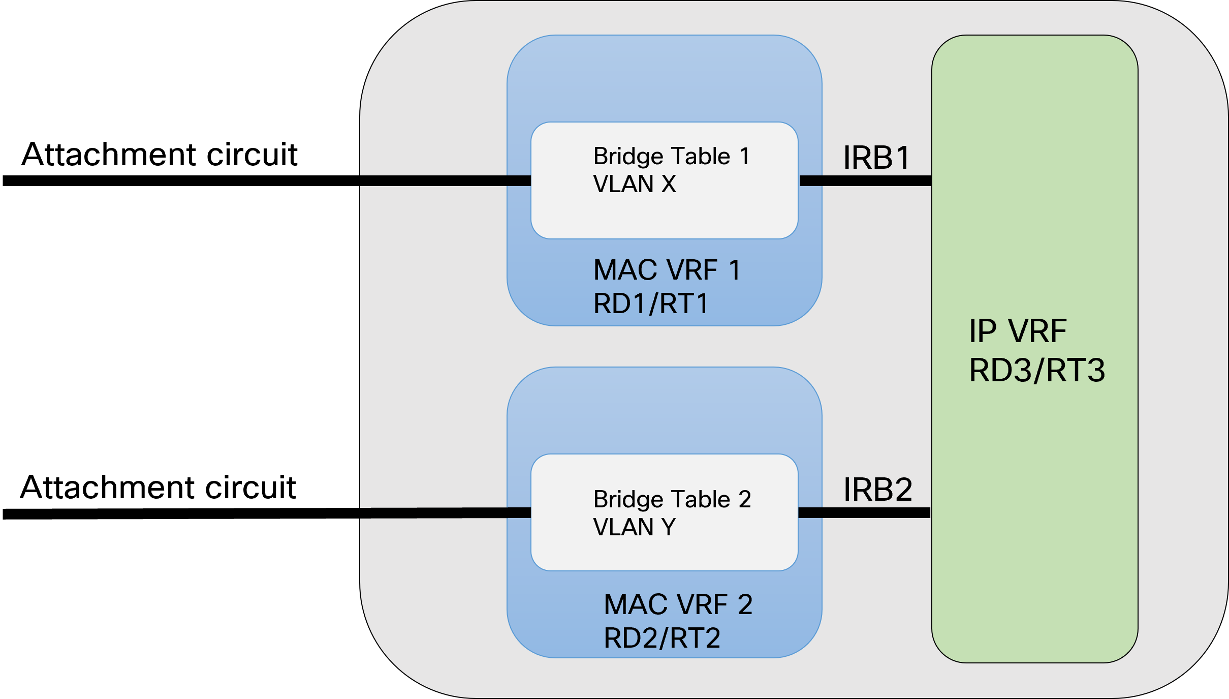
Let’s go through the terms used in the diagram and some additional ones:
- Attachment circuit – An interface that is associated with a bridge table. The AC that the packet arrived on is determined by examining the port, and optionally VLAN tag.
- Broadcast Domain – The Broadcast domain consists of all devices and hosts that would receive a broadcast frame when sent in that domain (assuming no ARP optimization features used). This is normally a VLAN, and it normally maps to one subnet. From a VXLAN perspective, it would be a L2 VNI. An EVI may contain one or more BDs depending on service model.
- Bridge Table – Bridge Table Continue reading
Bridging Packet Walk In VXLAN/EVPN Network
In this post I walk you through all the steps and packets involved in two hosts communicating over a L2 VNI in a VXLAN/EVPN network. The topology below is the one we will be using:
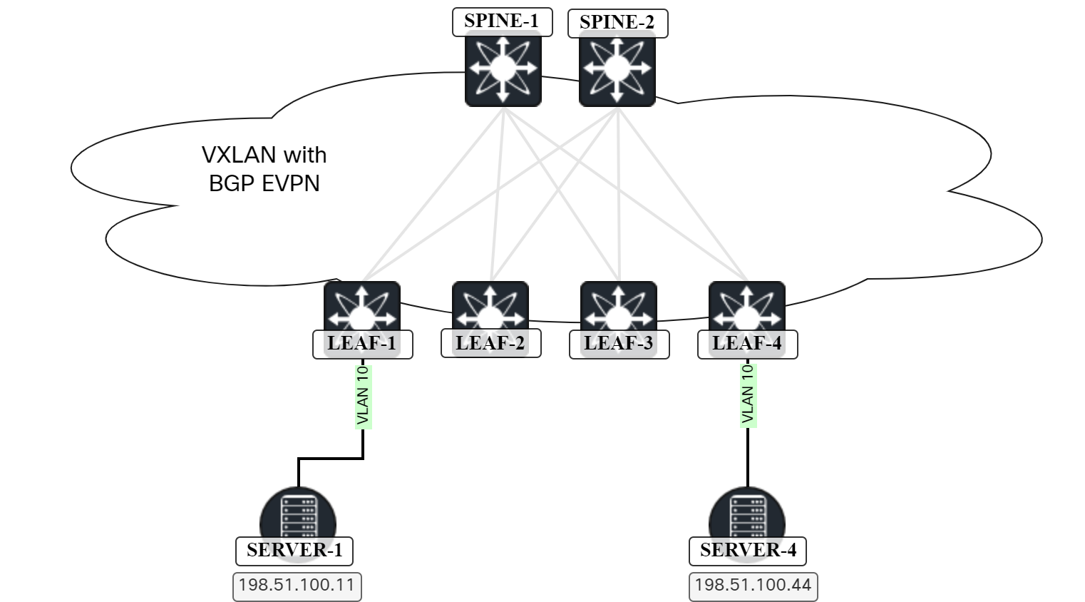
The lab has the following characteristics:
- OSPF in the underlay.
- Ingress replication for BUM traffic through the use of EVPN.
- ARP suppression is enabled.
- ARP cache is cleared on Server-1 and Server-4 before initating the packet capture.
- Server-1 is the host sourcing traffic by pinging Server-4.
Server-1 clears the ARP entry for Server-4 and initiates the ping:
sudo ip neighbor del 198.51.100.44 dev ens160
ping 198.51.100.44
PING 198.51.100.44 (198.51.100.44) 56(84) bytes of data.
64 bytes from 198.51.100.44: icmp_seq=1 ttl=64 time=6.38 ms
64 bytes from 198.51.100.44: icmp_seq=2 ttl=64 time=4.56 ms
64 bytes from 198.51.100.44: icmp_seq=3 ttl=64 time=4.60 ms
Below is packet capture showing the ARP request from Server-1:
Frame 7854: 60 bytes on wire (480 bits), 60 bytes captured (480 bits) on interface ens257, id 4
Ethernet II, Src: 00:50:56:ad:85:06, Dst: ff:ff:ff:ff:ff:ff
Address Resolution Protocol (request)
    Hardware type: Ethernet (1)
    Protocol type:  Continue reading
Why Is BFD More Light Weight Than Routing Hellos?
There are many articles on BFD. It is well known that BFD has the following advantages over routing protocol hellos/keepalives:
- BFD is more light weight than hellos/keepalives.
- Multiple clients can register to BFD instead of configuring each protocol with aggressive timers.
- On some platforms, BFD can be offloaded to the hardware instead of the CPU.
- BFD provides faster timers than routing protocols.
- BFD is less CPU intensive.
What does light weight mean, though? Does it mean that the packets are smaller? Let’s compare a BFD packet to an OSPF Hello. Starting with the OSPF Hello:
Frame 269: 114 bytes on wire (912 bits), 114 bytes captured (912 bits) on interface ens192, id 1
Ethernet II, Src: 00:50:56:ad:8d:3c, Dst: 01:00:5e:00:00:05
Internet Protocol Version 4, Src: 203.0.113.0, Dst: 224.0.0.5
Open Shortest Path First
    OSPF Header
        Version: 2
        Message Type: Hello Packet (1)
        Packet Length: 48
        Source OSPF Router: 192.168.128.223
        Area ID: 0.0.0.0 (Backbone)
        Checksum: 0x7193 [correct]
        Auth Type: Null (0)
        Auth Data (none): 0000000000000000
    OSPF Hello Packet
    OSPF LLS Data Block
There’s 114 bytes on the wire consisting of:
- 20 bytes of IP.
- 14 bytes of Ethernet.
- 80 bytes of Continue reading
Catalyst SD-WAN Enhanced Application Aware Routing
Traditionally, Cisco has leveraged BFD to monitor tunnels and their performance and Application Aware Routing (AAR) to reroute traffic. BFD has been used to measure:
- Latency.
- Loss.
- Jitter.
Additionally, BFD is also used to verify liveliness of the tunnels. This works well, but there are some drawbacks to using a separate protocol for measuring performance:
- You are adding control plane packets competing for bandwidth with packets in data plane.
- Sending control plane packets frequently may overload the control plane.
- This may lead to false positives.
- It’s not guaranteed that control plane packets and data plane packets are treated equally.
- AAR did take some time to react to poor transports as it had to collect enough measurements before reacting.
- AAR didn’t have a built-in dampening mechanism.
With the default BFD settings, BFD packets are sent every second. The default AAR configuration consists of six buckets that hold 10 minutes of data each. This means that with the default settings, AAR will react in 10-60 minutes depending on how poorly the transport is performing. The most aggressive AAR configuration recommended by Cisco was to have 5 buckets holding 2 minutes of data each. AAR would then react in 2-10 minutes which I Continue reading
Catalyst SD-WAN 20.13 – RBAC
Catalyst SD-WAN has supported Role Based Access Control (RBAC) for a long time. It has been possible to use predefined roles or create custom roles and defining what areas the user should have access to. However, before 20.13 it was not possible to define a scope. In large companies it’s quite common that one group manages one set of devices, for example all the sites in EU, all the sites in the US, etc. There may also be multiple business units within the company which may share some infrastructure but operate autonomously from each other where a BU should only have access to its own set of devices. As of 20.13, it is not possible to define scope when using RBAC in Catalyst SD-WAN.
There is another feature, called Network Hierarchy that is somewhat related to RBAC. When onboarding devices, you assign a Site ID to the device. The site is then assigned a name in the format of SITE_SiteID, for example SITE_10 when using a Site ID of 10. By default all sites belong to the global node as can be seen below:
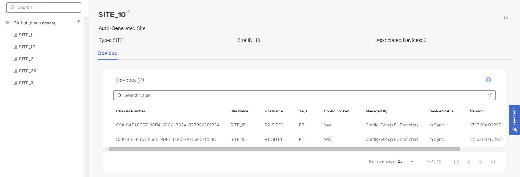
Note that it says Auto-Generated site. It is possible to edit the site Continue reading
NX-OS Forwarding Constructs For VXLAN/EVPN
In this post we will look at the forwarding constructs in NX-OS in the context of VXLAN and EVPN. Having knowledge of the forwarding constructs helps both with understanding of the protocols, but also to assist in troubleshooting. BRKDCN-3040 from Cisco Live has a nice overview of the components involved:
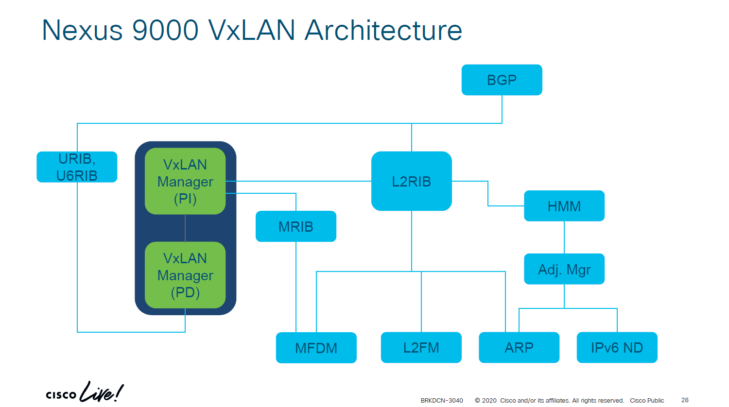
There are components that are platform independent (PI) and platform dependent (PD). Below I’ll explain what each component does:
- ARP – Information from ARP requests/responses is needed to build adjacencies. The information learned from ARP is used to populate IP address field in RT2 and hence also to populate the ARP suppression cache.
- IPv6 ND – ND fills the role of ARP, but for IPv6.
- Adjacency Manager – Resolves directly attached hosts MAC addresses.
- Host Mobility Manager – Tracks the endpoints and their movements.
- L2FM – The Layer2 Forwarding Manager. A platform dependent component that programs ASICs for L2 forwarding. Keeps track of MAC addresses, their placement and moves, and synchronizes this information across ASICS, line cards, and vPC peers when vPC is in use.
- MFDM – Multicast Forwarding Database Manager. A platform dependent component that programs ASICs with information to perform multicast forwarding.
- L2RIB – The component that handles Continue reading