VRF Without Route Target – Will the Route Be Exported?
Yesterday I posted a tricky question to Twitter. If you have a working VPNv4 environment and create a VRF with only a Route Distinguisher (RD) but without Route Targets (RT), will the route be exported? The answer may surprise you! The configuration supplied in the question was similar to the one below:
vrf definition QUIZ
 rd 198.51.100.1:100
 !
 address-family ipv4
 exit-address-family
!
interface GigabitEthernet2
 vrf forwarding QUIZ
 ip address 203.0.113.1 255.255.255.0
!
router bgp 65000
 !
 address-family ipv4 vrf QUIZ
  network 203.0.113.0
Notice how this VRF has a RD but no RT. Will this router, PE1, advertise the route into VPNv4? Most would say no, but the answer is yes. Let’s first check that we see the route locally on PE1 in VRF QUIZ:
PE1#show bgp vpnv4 uni vrf QUIZ 203.0.113.0
BGP routing table entry for 198.51.100.1:100:203.0.113.0/24, version 4
Paths: (1 available, best #1, table QUIZ)
  Advertised to update-groups:
     1
  Refresh Epoch 1
  Local
    0.0.0.0 (via vrf QUIZ) from 0.0.0.0 (198.51.100.1)
      Origin IGP, metric 0, localpref 100, weight 32768, valid, sourced, local, best
      mpls  Continue reading
Configuring EVPN on NX-OS
In this post we will configure EVPN on NX-OS. We will reuse the VXLAN topology from my previous post. The following will describe the setup in this post:
- VXLAN topology with OSPF as the IGP in the underlay using unnumbered links.
- EVPN in the overlay using iBGP.
- Spines acting as route reflectors.
- Separate loopbacks for IGP, BGP, and NVE.
- Ingress replication based on EVPN.
- Enhancements such as anycast gateway, ARP suppression, etc., will be covered in future posts.
The BGP topology is shown below:
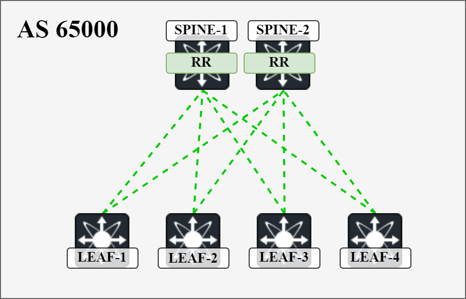
I will cover all the details of configuring EVPN and establishing the BGP sessions. We will then cover the actual exchange of routes in detail in separate posts in the future.
Starting out, the following globals and features need to be configured:

Next, let’s configure BGP on the spines with the following settings:
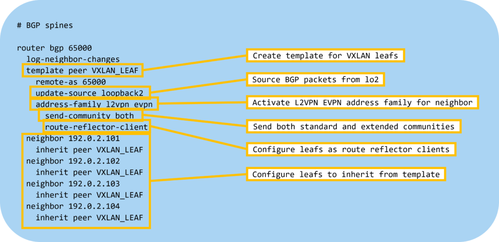
Then let’s configure BGP on the leafs:
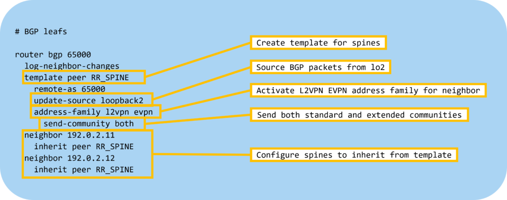
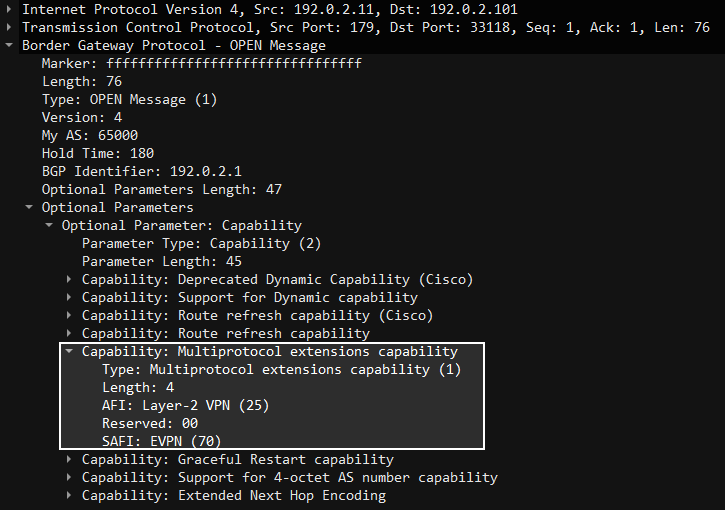
The devices will now advertise that they have AFI L2VPN and SAFI EVPN:
The BGP sessions are now up:
Leaf1# show bgp l2vpn evpn sum
BGP summary information for VRF default, address family L2VPN EVPN
BGP router identifier 192.0.2.3, local AS number 65000
BGP table version is 4, L2VPN EVPN config peers  Continue reading
Introduction to EVPN In VXLAN Networks
In previous posts I described VXLAN using flood and learn behavior using multicast or ingress replication. The drawback to flood and learn is that frames need to be flooded/replicated for the VTEPs to learn of each other and for learning what MAC addresses are available through each VTEP. This isn’t very efficient. Isn’t there a better way of learning this information? This is where Ethernet VPN (EVPN) comes into play. What is it? As you know, BGP can carry all sorts of information and EVPN is just BGP with support to carry information about VTEPs, MAC addresses, IP addresses, VRFs, and some other stuff. What does EVPN provide us?
- Ability to discover VTEPs.
- Messaging of MAC prefixes and IP prefixes.
- Reduced amount of flooding.
- Optionally ARP suppression.
Note that the use of EVPN doesn’t entirely remove the need for flooding using multicast or ingress replication. Hosts still need to use ARP/ND to find the MAC address of each other, although ARP suppression could potentially help with that. There may also be protocols such as DHCP that leverage broadcast for some messages. In addition, there may be silent hosts in the fabric where VTEP is not aware that the host is Continue reading
Trunk to Access – Will It Work?
Recently a posted a question to Twitter about connecting two Cisco Catalyst switches. One switch has already booted and has the following configuration:
interface GigabitEthernet0/0
 description SW02
 switchport mode trunk
 switchport trunk allowed vlan 1,10,20,30
 switchport nonegotiate
The other switch is connected to Gi1/0/48 and has just been powered on. It has no configuration so it is booting with the default configuration. The intention is to onboard a new switch via Catalyst Center using Plug and Play (PNP).
Based on the responses not many people were able to describe what would happen and why or why not this scenario would work. There are some interesting details here and before running into this scenario myself I thought that it might work. Before we can answer if it will work, let’s list what we know at this point in time about the two switches, SW01, and SW02. For SW01 we know that:
- The port is configured as a trunk.
- The VLANs allowed on the trunk are 1,10,20, and 30.
- DTP has been disabled.
- The native VLAN is 1.
For SW02 we know that:
- It will boot with all ports enabled.
- Those ports will be in VLAN 1.
- DTP is enabled on the Continue reading
How to Interview a Network Engineer Using a Single Scenario
Most organizations are terribly bad at interviewing people. They overcomplicate things by holding too many interviews (more than 2-3) and often focus their interview on trivia and memorization rather than walking through a scenario. Every interview should have some form of a scenario and a whiteboard if you are hiring a Network Engineer. Rather than overcomplicating things, here’s how you can interview someone using a single scenario that you can expand on and go to different depths at different stages depending on the focus of the role.
Scenario:
You are an employee working in a large campus network. Your computer has just started up and has not previously communicated with anything before you open your browser and type in microsoft.com.
Before any communication can take place, you need an IP address. What IP protocols are there? What are the main differences between the two?
Things to look for: IPv4 vs IPv6. ARP vs ND. DHCP vs RA. Broadcast vs multicast.
What methods are there of configuring an IP address?
Things to look for: Static IP vs DHCP vs RA.
When I need to communicate to something external, traffic goes through a gateway. What type of device would Continue reading
SPCOR Exam Experience by Nick Russo
On 31 October 2023, I took and passed the Implementing and Operating Cisco Service Provider Network Core Technologies (SPCOR) exam on my first attempt. Most of you know that I am recognized as an expert on Cisco Service Provider technologies given that I was one of the first to pass the new CCIE SPv4 exam in early 2016. Three months later, I released book of nearly 3,000 pages detailing all the technologies involved in that blueprint, going extremely deep into every topic. I later partnered with two other Service Provider experts to sell an ultimate study bundle that combined my textbook with their lab workbook. I think it’s fair to say that I should have crushed this exam, and although I did pass, it was far more difficult than I anticipated.
A few years ago, I also took the SCOR exam, but didn’t write a blog about it because I felt the exam was unremarkable. My friend Craig Stansbury has an excellent SCOR learning path at Pluralsight that I used to pass the exam on the first try, but on balance, it felt like a regular CCNP exam. SPCOR was a whole new class of difficulty. When I Continue reading
DCAUTO Exam Experience by Nick Russo
On 17 October 2023, I took and passed the Automating and Programming Cisco Data Center Solutions (DCAUTO) exam on my first attempt. This is the seventh DevNet exam I’ve passed. After the retirement of the Webex and IoT specialty exams, the Collaboration specialty and Expert exams remain the only two I haven’t attempted. Much like my experience with enterprise, service provider, and security automation, I have years of real-life experience automating various data center solutions, primarily by working with Nexus and NDO (formerly MSO). I’ve spoken about the topic on various podcasts and professional training courses many times. Believe it or not, I don’t have as much real-life automation experience with ACI or UCS, which are key data center products for Cisco, so I studied those areas intensely.
It’s worth mentioning that Cisco’s new certification road map introduces small changes at regular intervals to all of their certification exams. This is smart as it leads to less “blueprint shock” every few years, plus gives learners an opportunity to master the newest technologies in an incremental way. Because Cisco updated DCAUTO earlier this year, I took the v1.1 exam. I’m not kidding when I say the exam was Continue reading
Forwarding BUM Frames in VXLAN Network With Static Ingress Replication
In the last post we used multicast to forward BUM frames. In this post, static ingress replication is used which removes the requirement for multicast in the underlay. Before setting this up, let’s do a comparison of multicast vs ingress replication. To make this interesting, let’s use a larger topology consisting of 2 Spines and 32 Leafs:

Assume that all Leafs have the same VNIs. In a scenario with multicast, Leaf-1 sends for example an ARP request encapsulated in multicast towards Spine-1. This is a single frame. Spine-1 then replicates this frame and sends it on all its links towards the Leafs:

This is very efficient as a single frame is sent by Leaf-1 and then 31 copies are sent on the other links to the Leafs. If the ARP request is 110 bytes, then a total of 32 x 110 = 3520 bytes have been consumed to send this ARP request. This is optimal forwarding from a resource consumption perspective and one of the strengths of multicast. Now let’s compare that to ingress replication. With ingress replication, Leaf-1 sends 31x copies of the frame (with different destination IP) towards Spine-1. Spine-1 then forwards those frames on each link towards Continue reading
Forwarding BUM Frames in VXLAN Network With Multicast in Underlay
There are two main methods that can be used to forward broadcast, unknown unicast, and multicast (BUM) frames in a VXLAN network:
- Ingress replication.
- Multicast in underlay.
In this post, we take a detailed look at how multicast can be used to forward BUM frames by running multicast in the underlay. We are using the topology from my Building a VXLAN Lab Using Nexus9000v post. The Spine switches are configured using the Nexus feature Anycast RP. That is, no MSDP is used between the RPs. To be able to forward broadcast frames such as ARP in our topology, the following is required:
- The VTEPs must signal that they want to join the shared tree for 239.0.0.1 (to receive multicast) using a PIM Join.
- The VTEPs must signal that they intend to send multicast for 239.0.0.1 on the source tree using a PIM Register.
- The RPs must share information about the sources that they know of by forwarding PIM Register messages.
- The VTEP must encapsulate ARP packets in VXLAN and forward in the underlay using multicast.
The Leaf switches have the following configuration to enable multicast:
ip pim rp-address 192.0.2.255 group-list 224. Continue reading
Path Hunting in BGP
BGP is a path vector protocol. This is similar to distance vector protocols such as RIP. Protocols like these, as opposed to link state protocols such as OSPF and ISIS, are not aware of any topology. They can only act on information received by peers. Information is not flooded in the same manner as IGPs where a change in connectivity is immediately flooded while also running SPF. With distance and path vector protocols, good news travels fast and bad news travels slow. What does this mean? What does it have to do with path hunting?
To explain what path hunting is, let’s work with the topology below:
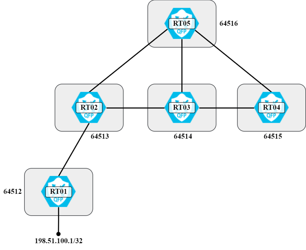
With how the routers and autonomous systems are connected, under stable conditions RT05 will have prefix 198.51.100.1/32 via the following AS paths:
- 64513 64512
- 64514 64513 64512
- 64515 64514 64513 64512
This is also shown visually in the following diagram:
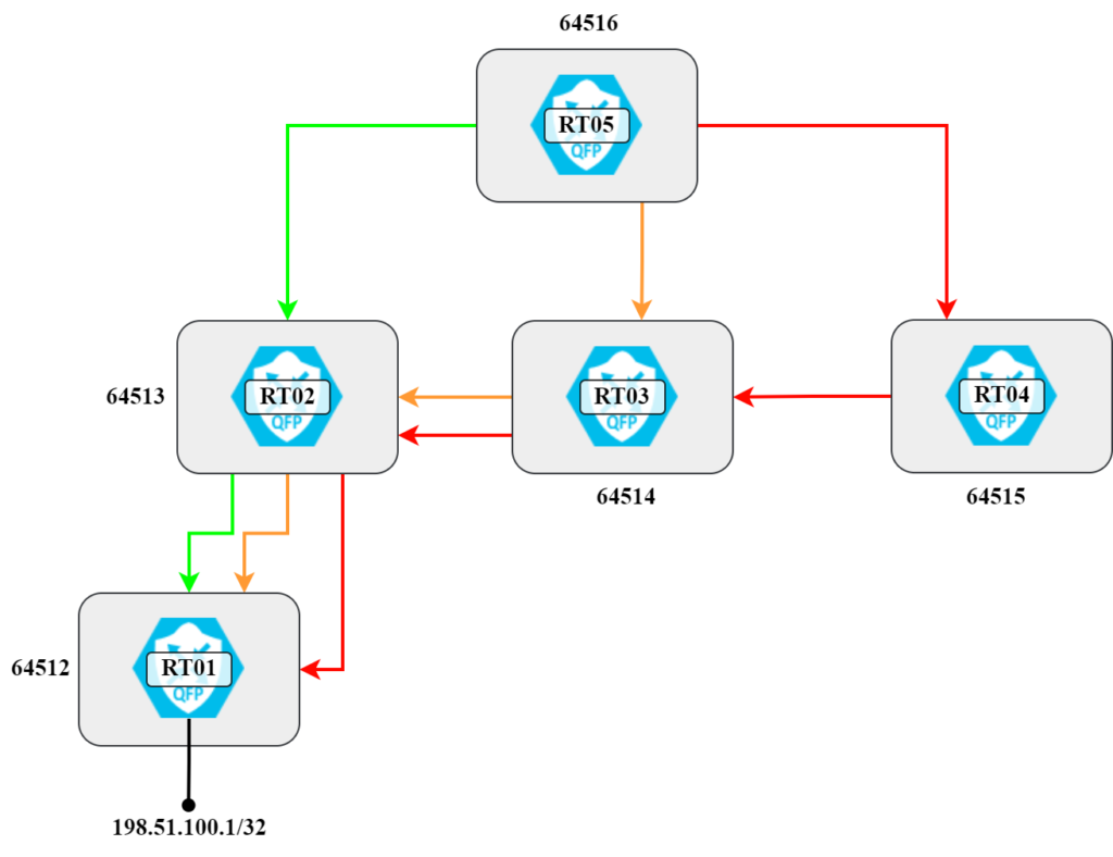
There’s a total of three different paths, sorted from shortest to longest. Let’s verify this:
RT05#sh bgp ipv4 uni
BGP table version is 11, local router ID is 192.168.128.174
Status codes: s suppressed, d damped, h history, * valid, > best, i - internal,
              r RIB-failure, S  Continue reading
Valley-free Routing in Leaf and Spine Topology
Valley-free routing is a concept that may not be well known but that is relevant to datacenter design. In this post, we’ll valley-free routing based on a leaf and spine topology.
There are many posts about leaf and spine topology and the benefits. To summarize, some of the most prominent advantages are:
- Predictable number of hops between any two nodes.
- All links are available for usage providing high amount of bisection bandwidth (ECMP).
- The architecture is easy to scale out.
- Redundant and resilient.
Now, what does this have to do with valley-free routing? To understand what valley-free routing is, first let’s take a look at the expected traffic flow in a leaf and spine topology:
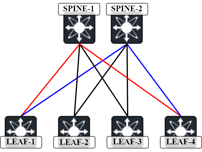
For traffic between Leaf1 and Leaf4, the two expected paths are:
- Red path – Leaf-1 to Spine-1 to Leaf-4.
- Blue path – Leaf-1 to Spine-2 to Leaf-4.
This means that there is only one intermediate hop between Leaf1 and Leaf4. Let’s confirm with a traceroute:
Leaf1# traceroute 203.0.113.4
traceroute to 203.0.113.4 (203.0.113.4), 30 hops max, 48 byte packets
 1  Spine2 (192.0.2.2)  1.831 ms  1.234 ms  1.12 ms
 2  Leaf4 (203. Continue reading
Nexus9000v and “Missing” Routes
I have built my lab for VXLAN on the Nexus9300v platform. Since I have a leaf and spine topology, there are ECMP routes towards the spines for the other leafs’ loopbacks. When performing labs though, I noticed that I didn’t have any ECMP routes in the forwarding table (FIB). They are in the RIB, though:
Leaf1# show ip route 203.0.113.4
IP Route Table for VRF "default"
'*' denotes best ucast next-hop
'**' denotes best mcast next-hop
'[x/y]' denotes [preference/metric]
'%<string>' in via output denotes VRF <string>

203.0.113.4/32, ubest/mbest: 2/0
    *via 192.0.2.1, Eth1/1, [110/81], 1w0d, ospf-UNDERLAY, intra
    *via 192.0.2.2, Eth1/2, [110/81], 1w0d, ospf-UNDERLAY, intra
There is only one entry in the FIB, though:
Leaf1# show forwarding route 203.0.113.4?
  A.B.C.D      Display single longest match route
  A.B.C.D/LEN  Display single exact match route

Leaf1# show forwarding route 203.0.113.4/32

slot  1
=======


IPv4 routes for table default/base

------------------+-----------------------------------------+----------------------+-----------------+-----------------
Prefix            | Next-hop                                | Interface            | Labels          | Partial Install
------------------+-----------------------------------------+----------------------+-----------------+-----------------
203.0.113.4/32       192.0.2.1                                 Ethernet1/1
This seemed strange to me and I was concerned that maybe something was Continue reading
Is One Protocol Simpler Than Two?
I’ve been in a lot of interesting discussions the last couple of days on what protocol to use for the underlay when building a VXLAN datacenter network. Do you use an IGP such as OSPF or ISIS or do you use BGP? A common argument for BGP is that running one protocol is less complex than two. Is it, though?
We can argue about if OSPF or BGP is the more well known protocol. What I think is going on here though is that OSPF is perceived as complex due to the following reasons:
- Utilizes both unicast and multicast for messaging.
- Maintains a link state database and runs SPF to calculate best paths.
- Different LSA types and flooding behavior.
- Does not advertise routes.
On the other hand, BGP has the following characteristics:
- Utilizes only unicast for messaging.
- Rides over TCP.
- Advertises prefixes (NLRI).
Is OSPF complex? That’s debateable but everything is difficult if you don’t know it well enough. If you don’t know your way around the LSDB then it can be difficult to understand how routes get into the RIB and later FIB. Not knowing a protocol doesn’t make it complex, though. I would argue that someone with the Continue reading
Choosing the Underlay Protocol in a VXLAN Network
When building a VXLAN network, what are the considerations for choosing the underlay protocol such as OSPF, IS-IS, or BGP? You obviously want the design to be supported by your vendor of choice. Your staff should also be able to support the design. Although I think it’s reasonable to expect from a Network Engineer that they have some level of knowledge in OSPF and BGP and that this should not be the main deciding factor. Let’s dive into the different protocols and walk through their characteristics and how they can be used as underlay protocols in a VXLAN network. I will compare OSPF to BGP as ISIS basically provides all the benefits of OSPF with some additional ones, but with less support from vendors, and it’s a protocol less known by most Engineers.
OSPF
Protocol overview – OSPF is a link state protocol that builds a Link State Database (LSDB) and runs the Shortest Path First (SPF) algorithm based on Dijkstra’s work to calculate the shortest path. It relies on flooding Link State Advertisements (LSAs). All routers in an area need an identical LSDB.
Ajacencies and transmitting protocol packets – OSPF transmits packets over IP in IP protocol 89. It Continue reading
Unnumbered Links In OSPF
This post is going to be a real deep dive! First, I want to send my sincere thanks to the maestro Peter Palúch and the guru Ivan Pepelnjak for helping me research this topic. Ivan wrote a couple of great posts on unnumbered links:
- Packet Forwarding and Routing over Unnumbered Interfaces
- Running OSPF over Unnumbered Ethernet Interfaces
In VXLAN fabrics, it is quite common to build the underlay using unnumbered links. The concept is not new. In the past, unnumbered links were mainly used with point to point serial links using encapsulation such as Point-to-Point Protocol (PPP). There was a time before variable length subnet masks where addressing interfaces could be very wasteful. Using unnumbered links reduced the need for addressing. It was generally not allowed on multi access interfaces such as Ethernet, though. Even though we often use Ethernet as point to point links.
What benefits do unnumbered links provide in today’s networks? There are a few:
- Reduce the number of IP addresses needed to address links.
- Less unique configuration for each device.
- Fewer lines of configuration.
Let’s dive deeper into each of these:
Reduced need of IP addresses – While these may be private IP addresses, it still Continue reading
Building a VXLAN Lab Using Nexus9000v
As I dive into the world of VXLAN, I will need a lab as that is the best way to deepen the learning process and to get hands-on experience with a protocol. I will be building a Cisco Nexus9000v lab in VMware ESX but the same images can be used in CML, EveNG, GNS3, etc. The lab is based on the following topology:
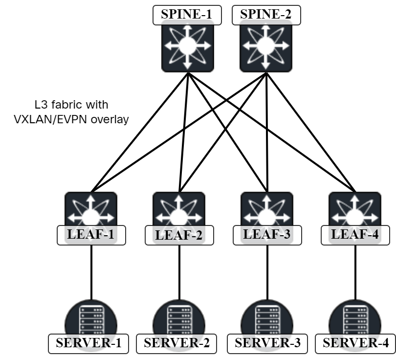
The specific platform I’ll use is the Nexus9300v which has the following requirements:
- 1 vCPU (2 recommended).
- 10 GB of RAM (12 GB recommended).
Note that there is also a Nexus9500v image which is a 16-slot modular chassis. As I have no need for multiple slots, and it requires more CPUs, I will not be using this image.
The specific image I am using is nexus9300v64.10.2.5.M.ova, which is NX-OS version 10.2.5.
Deploying the OVA can take some time but is otherwise straightforward. Refer to my post on caveats for more details.
I have mapped the different NICs to different port groups:
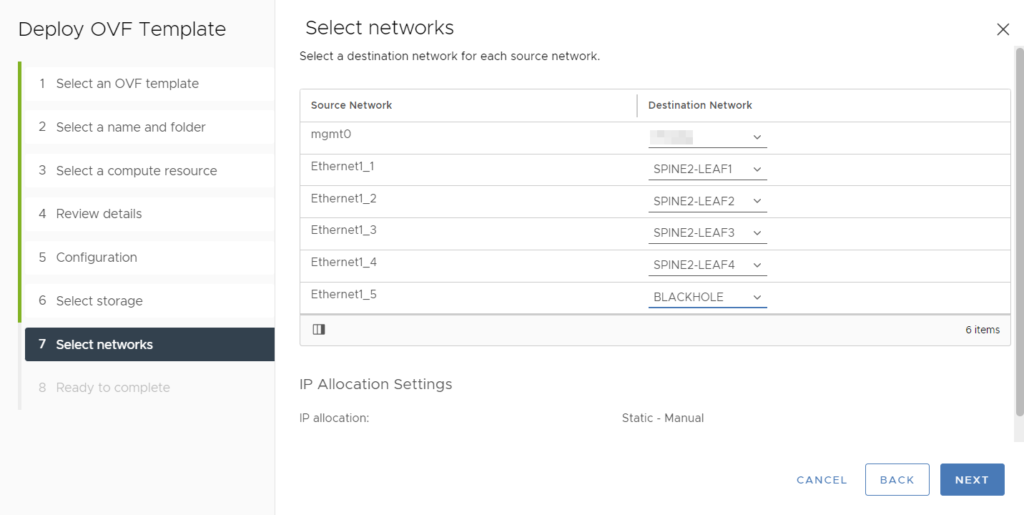
The mgmt0 interface is mapped to my management network so that I can SSH to the devices. I have also created specific port groups for the interconnections between leaf Continue reading
Caveats When Deploying Nexus9000v
As I’m building a VXLAN lab based on Nexus9000v, I ran into some caveats while deploying. Some things are related to ESX (vSphere) only while others apply to also other platforms.
The boot process for Nexus9000v is a bit special. It requires using a serial console to access switch prompt and from there booting the NX-OS image. There are a few steps to enable this in vCenter. For the VM that was deployed using the OVA, edit settings of the VM and go to Virtual Hardware -> Serial port 1:

Use the following settings:
- Use Network.
- Direction – Server.
- Port URI – telnet://<portnumber>.
Note that when selecting a port number, it must be a port above 1024.
Next, under VM Options, go to Advanced and select Edit Configuration…

Click Add Configuration Params and add the following entry:
efi.serialconsole.enabled with a value of TRUE:

The server also needs to have firewall ports open. This is done by going to Configure -> System -> Firewall:

Make sure that VM serial port is enabled.
Then, power on the device which will boot to Loader. Boot on the image stored on bootflash:
Loader Version 5.9.3.94

loader  Continue reading
Introduction to VXLAN
In the previous post, we looked at some of the challenges with L2-based networks. Now let’s start diving into what VXLAN is and what it can provide. First, let’s talk about overlays.
Overlays
Overlays are not new. We have had overlays for many years. The most well known ones are probably GRE and MPLS. In general, overlays are used to create a level of indirection that extends network capabilities. For example, MPLS L3 VPNs provided some of these capabilities to IP networks:
- Segmentation.
- Overlapping IPs.
- Custom topologies.
- Scaling.
- Multihoming.
With overlays, intelligence is often pushed to the edge of the network while intermediate devices can be “dumb”. This can reduce costs as not all devices need the advanced features. How does an overlay work? To create the indirection, the original frame or packet needs to be encapsulated. Depending on the type of overlay, the frame or packet could get encapsulated into another frame or packet. The transport between the overlay nodes is called the underlay. This is the network that transports packets between the nodes. For VXLAN, this is a layer 3 network.
Because overlays encapsulate frames or packets, the size of the frame or packet will increase. To compensate Continue reading
VXLAN/EVPN – What Are the Challenges in L2-based Networks?
Before diving into a new technology, it is always useful to understand the previous generation of technology, what the limitations where, and how the new technology intends to overcome them. In this post, let’s look at what some of the challenges were with L2-based networks and how VXLAN/EVPN can overcome them. Before starting, I want to balance the messaging a bit on the bad reputation that STP gets:
- Radia Perlman did an excellent job with what was available at that time.
- A lot of the bad reputation comes from a misunderstanding of the protocol.
- STP-based networks can run just fine but they are often misconfigured (related to the point above).
- Many issues come from misbehaving end user devices where protection mechanisms have not been implemented (see the point above).
- It’s natural for technologies to evolve as more compute becomes available and we gain experience.
Keep in mind that the original 802.1D standard was published in 1990. This was long before internet was generally available and our networks were critically important to us. At that time we didn’t measure outages in seconds or even minutes. That said, let’s look at the limitations of a traditional L2 network.
Convergence – In Continue reading
Python – Using the IP Address Module to Calculate IPs
I’m currently preparing for a network rollout and the preparation includes assigning subnets to the sites. There are subnets needed for management, wired users, wireless users, guests, and so on. Once subnets have been assigned, for some of the subnets, DHCP scopes need to be created. The team managing the server has requested that information on the subnets, gateway, and what IP the scope begins and ends with be provided as a CSV file. This will allow for easily importing the scopes into the server.
For my scenario, I have the information in a spreadsheet and I’m accessing the information using the openpyxl project. I am then using the ipaddress library to take the prefix from the spreadsheet and performing various calculations. Why use Python for this?
- Writing CSV is time consuming for humans.
- Although I’m quite good at performing calculations, I’m not better than a computer.
- Using code means consistent output that is less error prone.
The goal is to create a line of CSV that looks like this:
VLAN 100 User,192.0.2.64,255.255.255.192,192.0.2.65,192.0.2.75,192.0.2.126,US0100 NY,example.com,
This line consists of:
- Subnet name.
- Network.
- Network mask.
- Gateway.
- Continue reading